Control System for a Remote Vehicle

a technology for controlling systems and vehicles, applied in the direction of mechanical control devices, process and machine control, instruments, etc., can solve the problems of large equipment and gear burdening users, limited range of motion for military personnel, and a certain amount of strength, and achieve the effect of convenient removal

Inactive Publication Date: 2008-10-30
FLIR DETECTION
View PDF99 Cites 113 Cited by
  • Summary
  • Abstract
  • Description
  • Claims
  • Application Information

AI Technical Summary

Benefits of technology

[0010]Accordingly, the present invention provides a control system for operation of a remote vehicle comprises a twin-grip hand-held controller having a volume of less than 1 liter and a weight of less than 1 lb. The twin-grip hand-held controller includes: a left grip shaped to be held between a user's left little finger, ring finger, and the ball of the thumb, leaving the user's left index finger, middle finger, and thumb free; a left control zone adjacent to the left grip, including a first analog joystick and a first 4-way directional control manipulable by the left thumb, and a left rocker control located on a shoulder portion of the controller; a right handed grip shaped to be held between the user's right little finger, ring finger, and the ball of the thumb, leaving the user's left index finger, middle finger, and thumb free; a right control zone adjacent the right grip, including a ...

Problems solved by technology

Users can be burdened by large amounts of equipment and gear.
Extensive gear can result in limited range of motion for military personnel, complicating fast transitions into various firing positions as well as entering and exiting vehicles.
Still further, military personnel do not want to be targeted as a specialized soldier (remote vehicle operator) and there...

Method used


Image

  • Control System for a Remote Vehicle
  • Control System for a Remote Vehicle
  • Control System for a Remote Vehicle

Examples


Embodiment Construction

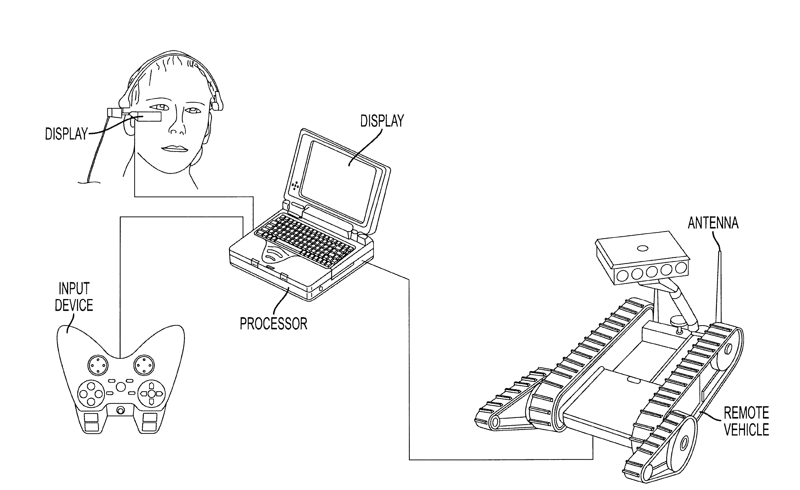
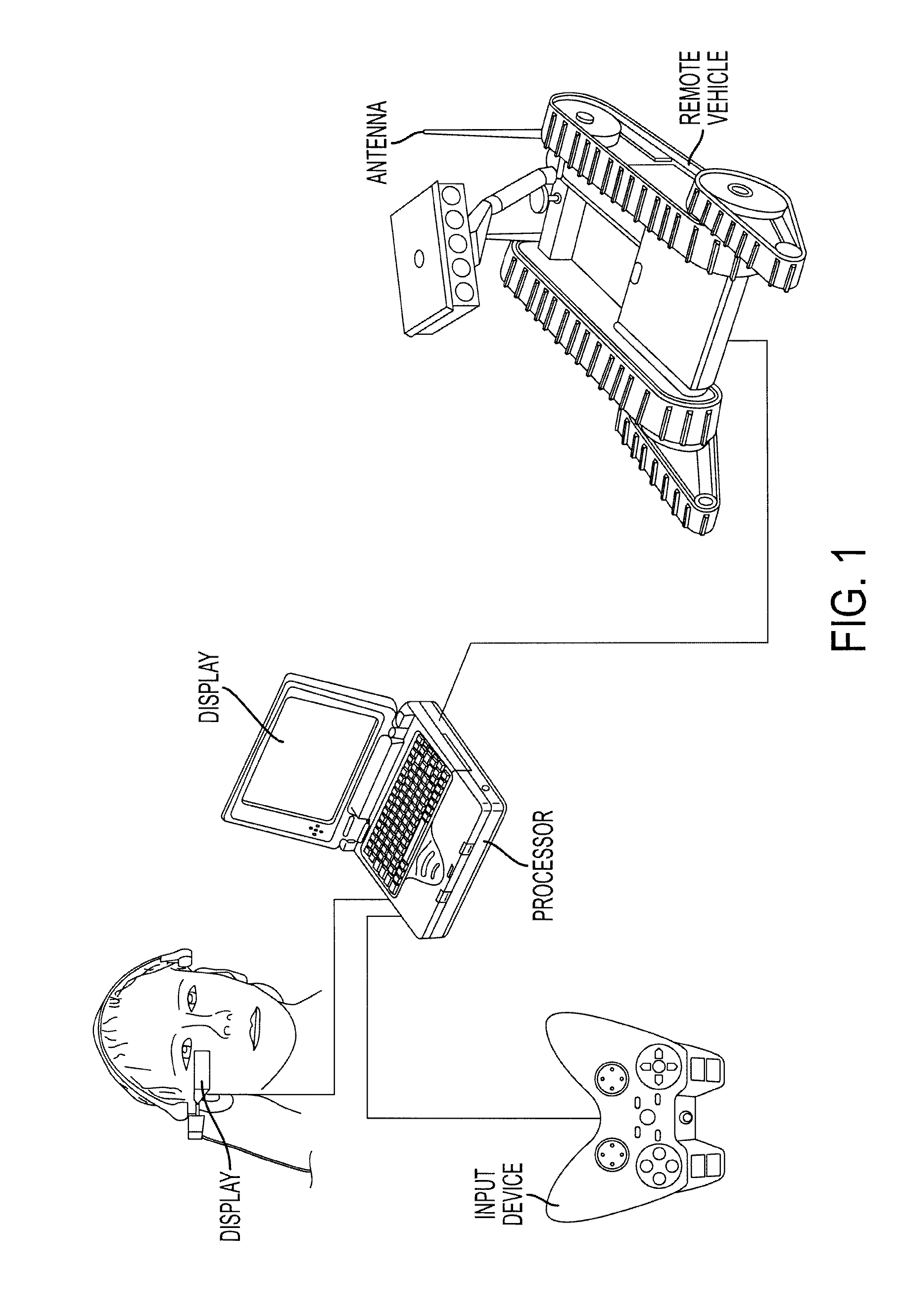
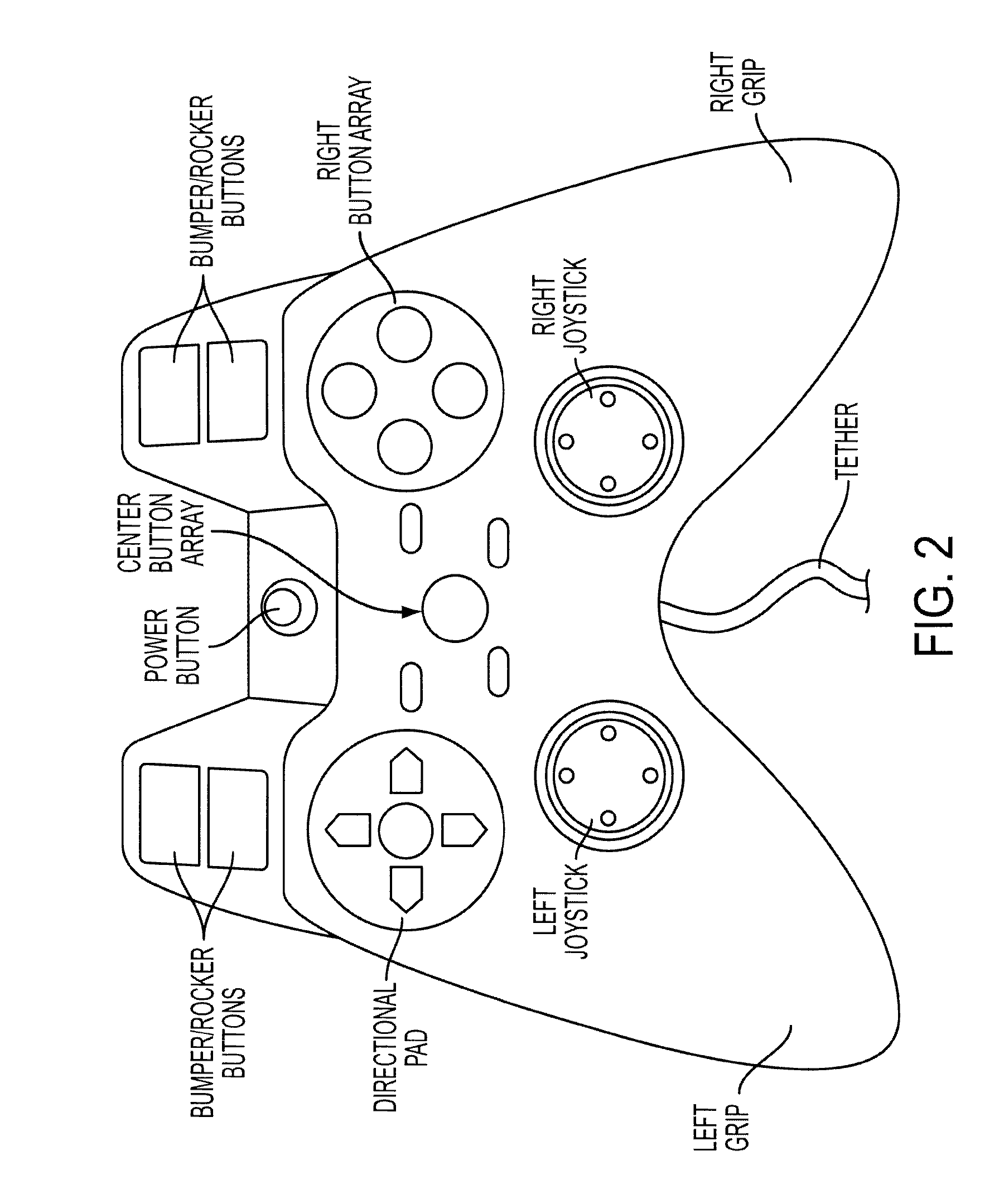
[0047]A control system of the present invention includes an unobtrusive, highly mobile control system that provides the user with a remote vehicle such as a teleoperated remote control vehicle (embodied herein by a robot) operating experience that seamlessly integrates with the user's other tasks and duties. Situational awareness is minimally compromised when operating the system, as it is critical for the user to be aware of his surroundings. Basic components of the control system, which are illustrated in FIG. 1, include a display, an input device, a processor, an antenna / radio (for wireless communication), and software. In an embodiment of the invention, a head-mounted display provides video display from one or more remote vehicle cameras. A hand-held controller, preferably having a twin-grip design, includes controls to drive, manipulate, and monitor the robot and its payloads. Audio may additionally be provided via the hand-held controller, the display, or dedicated listening d...


PUM


Abstract

A control system for operation of a remote vehicle comprises a twin-grip hand-held controller having a volume of less than 1 liter and a weight of less than 1 lb. The twin-grip hand-held controller includes: a left grip shaped to be held between a user's left little finger, ring finger, and the ball of the thumb, leaving the user's left index finger, middle finger, and thumb free; a left control zone adjacent to the left grip, including a first analog joystick and a first 4-way directional control manipulable by the left thumb, and a left rocker control located on a shoulder portion of the controller; a right handed grip shaped to be held between the user's right little finger, ring finger, and the ball of the thumb, leaving the user's left index finger, middle finger, and thumb free; a right control zone adjacent the right grip, including a second analog joystick and a second 4-way directional control manipulable by the right thumb, and a right rocker control located on a shoulder portion of the controller; a tether zone between the left control zone and the right control zone, including a tether anchor configured to tether the hand controller between the left grip and the right grip and to permit the hand controller to hang with the left grip and right grip pointing upward; a tether extending from the tether anchor to the right shoulder of an operator, the tether including a strain relief section. A quick-release pad is worn on an operator's chest, the quick-release pad including a first fastener for affixing the quick-release pad to available mounts on the operator, and a second quick-release fastener for holding the hand-held controller to the quick-release pad to be readily removable by pulling on the hand-held controller.

Description

BACKGROUND OF THE INVENTION[0001]1. Field of the Invention[0002]The present invention relates generally to controlling a remote vehicle, and more particularly to an improved system for remotely controlling one or more vehicles in real time from a dismounted position.[0003]2. Description of Related Art[0004]Improving user experience with remote vehicle interfaces is an ongoing area of development. Particular areas of concern include optimizing mission-critical response time, minimizing training and logistics support, minimizing complexity, attaining an ideal weight, size, and simplicity while increasing durability and reliability, and the ability to integrate the control system into gear normally worn or carried by the user.[0005]Users can be burdened by large amounts of equipment and gear. For example, typical military gear includes an Outer Tactical Vest (OTV) and weapons such as an M16 or an M4 carbine. Gear often additionally includes one or more of ammunition, first aid kits, hi...

Claims


Application Information

Patent Timeline
IPC IPC(8): G06F3/033
CPCG05D1/0016G05D1/0038G05D1/0044G05D2201/0209G08C19/16G05G1/01G05G1/02G05G1/04G08B5/36G08C17/02
Inventor ROBBINS, MICHAEL A.KENYON, SAMUEL H.GERSON, ROGERWOODBURY, TRAVISLEDOUX, MELISSA N.
Owner FLIR DETECTION
Why Eureka
Try Eureka