
Visual Shields With Technology Including Led Ladder, Network Connections and Concertina Effects

a technology of led ladders and visual shields, applied in the direction of electrical controllers, lighting support devices, coupling device connections, etc., can solve the problems of inflexibility, difficult, costly, time-consuming and laborious, and the reconfiguration of commercial interiors is a time-consuming and laborious undertaking

Inactive Publication Date: 2008-10-30
SKIDMORE MARSHA +5
View PDF1 Cites 47 Cited by
  • Summary
  • Abstract
  • Description
  • Claims
  • Application Information

AI Technical Summary

Benefits of technology

[0041]The lighting system can include means for supporting the lighting elements in the strip units in a manner so as to vary the spatial density of the lighting elements and the strip units within the overhead lighting plane. The spatial density is configured so that the strip units include a spatial area of the overhead lighting plane which is a relatively small percentage of the entirety of the spatial area of the overhead lighting plane. The lighting elements in the strip units are spaced so as to further provide for a relatively continuous ceiling plane of light, while reducing shadow effects.
[0049]The system also includes means for a user to vary the density of the light by varying the number of strip units associated with the LED ladder panel, and also varying lateral distances between adjacent ones of the strip units. The system can include frame connection means for connecting each of the strip units to the overhead frame. When the lighting elements in the strip units are assembled, light intensity can be varied by modifying the number of individual lighting elements carried by each of the strip units. The strip units can be connected to the frame connection means with a spatial density so as to provide light intensity when the lighting elements are activated, and so as to also permit passage of fixtures through the lighting plane from above and below the lighting plane.

Problems solved by technology

Given the use of stationary walls and heavy equipment, any reconfiguration of a commercial interior was a time-consuming and costly undertaking.
These factors have added considerably to the complexity of planning and managing commercial interiors.
The confluence of these conditions has resulted in commercial interiors being inflexible and difficult and costly to change.
Further, known systems typically do not address issues associated with ceiling structures, such as interchangeability, lighting, acoustical properties and the like.
However, open ceiling architecture can present problems with respect to acoustical properties and, for some, may not be aesthetically pleasing.
In addition to the foregoing issues, many known ceiling structures are substantially difficult to reconfigure, once initially assembled and put into place.
Accordingly, with this difficulty of reconfiguration, corresponding difficulties arise in the event that modifications are required in lighting, HVAC duct work or sprinkler locations.
In addition, reconfiguration of most known ceiling structures may involve substantial expense.
Also, as with other elements of known architectural interiors, reconfiguration may require substantial time and involve personnel having technical expertise.
Lighting associated with such structures also has the same problems with respect to potential need for change.
Also, when ceiling systems are first designed by the designers, architects and engineers, it may be several years before the building is actually commissioned and tenants occupy the building.
Other issues also arise with respect to ceiling structures.
Other disadvantages exist with respect to current ceiling systems.
Still further, known ceiling systems do not lend themselves to interchangeability of ceiling system components.
In addition, known ceiling systems do not have the capability of modifications in color, configuration and the like based on external environmental characteristics, such as time of day, particular season and other changes.
Still further, many of the architectural interiors in existence today actually result in an “overperformance.” That is, ceilings have weight, bulk and other size parameters which are clearly unnecessary for their desired functionality.
Their cost is significant.
This cost occurs not only from initial acquisition prices, but also, as a result of their lack of true flexibility, from costs associated with moving or reconfiguring the ceiling systems.
Also, in part, additional costs result from the fact that reconfiguration of such ceiling systems often results in waste of component parts.
Still further, known ceiling systems for many reasons (including those previously stated herein), do not lend themselves to any type of “rapid” reconfiguration.
In fact, they may require a significant amount of work to reconfigure.
Also, reconfiguration of known ceiling systems may involve additional physical wiring or substantial rewiring for their lighting.
Still further, although these ceiling systems may involve lighting controllable by a workspace user, many environmental functions remain centrally controlled, often in locations substantially remote from the architectural interior being controlled.
Even further, however, difficulties can arise in known ceiling systems when environmental characteristic control is provided within a general space of an occupant.
However, if the lighting is moved to different ceiling areas, the switch controlling the lighting may no longer be located in a functionally “correct” position.
In this regard, known systems have no capability of providing any relatively rapid reconfiguration of controlling / controlled relationships among functional elements, such as switches, ceiling lights and the like.
Another significant disadvantage with known ceiling systems relates to their lack of development in light of advances in technology.
However, many of these technological advances have modified today's business, educational and personal work practices.
However, most of today's ceiling systems do not provide for availability of such features.
In addition, known systems do not provide any other features which will facilitate efficiency in today's new work practices, such as digital programming of lighting.
In part, disadvantages exist because of today's business practices.
In the past, problems associated with difficulty in reconfiguration of architectural interiors, and lack of in situ control of a location's environmental conditions, may not have been of primary concern.
However, today's business climate often involves relatively “fast changing” architectural interior needs.
However, when these structures, which can be characterized as somewhat “permanent” in most buildings (as described in previous paragraphs herein), are designed, the actual occupants may not move into the building for several years.
Needless to say, in situations where the building will not be commissioned for several years after the design phase, the ceiling systems of the building may not be appropriately laid out for the actual occupants.
That is, the prospective tenants' needs may be substantially different from the designers' anticipated ideas and concepts.
However, as previously described herein, most architectural interiors permit little reconfiguration after completion of the initial design.
Reconfiguring of ceiling systems in accordance with the needs of a particular tenant can be extremely expensive and time consuming.
Also, if the space was to be made available to tenants, the space is providing no positive cash flow to the buildings' owners.
However, many business organizations today experience relatively rapid changes in growth, both positively and negatively.
When these changes occur, again it may be difficult to appropriately modify the architectural interior so as to permit the occupant to expand beyond its original architectural interior or, alternatively, be reduced in size such that unused space can be occupied by another tenant.
Other problems also exist with respect to the layout and organization of today's architectural interiors.
To modify these control relationships in most architectural interiors requires significant efforts.

Method used


Image

  • Visual Shields With Technology Including Led Ladder, Network Connections and Concertina Effects
  • Visual Shields With Technology Including Led Ladder, Network Connections and Concertina Effects
  • Visual Shields With Technology Including Led Ladder, Network Connections and Concertina Effects

Examples


embodiment 300

[0183]FIGS. 20 and 21 illustrate another embodiment of a ceiling configuration, identified as ceiling configuration 300. In this particular instance, a series of rigid fins 310 form a rectangular configuration around individual ones of the linear LED lighting modules 144. However, unlike certain of the other ceiling embodiments described herein, embodiment 300 is configured so that each linear LED lighting module 144 is turned on its side, with the strips of LED's 152 have a different directional configuration. In this case, the ceiling configuration 300 includes the rigid fins 310 in a rectangular configuration, with the fins 310 also being constructed of a translucent Lexan® material.

[0184]FIGS. 22, 23 and 23A illustrate a further ceiling configuration 320 which may be utilized in accordance with the invention. As illustrated in these drawings, the ceiling configuration 320 includes a series of parallel and spaced apart linear air tubes 330. The linear air tubes 330 are mounted so...

embodiment 340

[0186]FIGS. 24, 25 and25A illustrate a further ceiling configuration 340. The configuration 340 is somewhat similar to that illustrated in FIG. 22, in that the configuration 340 utilizes linear air tubes 350 for purposes of providing the ceilings. However, unlike FIG. 22, the ceiling embodiment 340 also utilizes what are referred to as round marker LED lighting modules 360. Such lighting modules 360 have a structural configuration as primarily illustrated in FIGS. 25 and 25A. Again, the linear air tubes 350 may be constructed of polyethylene air tubes.

[0187]FIGS. 26, 27 and 27A illustrate a further embodiment of a ceiling configuration in accordance with the invention, identified as ceiling configuration 400. In this particular instance, the ceiling configuration 400 employs round marker LED lighting modules 360, corresponding to the round marker LED lighting modules 360 previously described with respect to FIGS. 24, 25 and 25A. However, unlike the ceiling embodiment 340 illustrated...

second embodiment

[0250]FIG. 49A illustrates a network connection configuration, having substantial similarities to the network connection configuration 810. The network connection configuration illustrated in FIG. 49A is identified as network connection configuration 850. The network connection configuration 850 comprises a layout similar to configuration 810 and, for that reason, like reference numerals are utilized to identify comparable elements of the configurations 810 and 850. The primary distinction between these two particular configurations relates to the manner in which AC power is applied as input power to the electronics units 814.

[0251]More specifically, with reference to connection configuration 810 in FIG. 49, incoming building power is received separate and apart from the AC power cables running through the main rails 652. Instead, the power is applied directly to the electronics unit 814 from the incoming power conduits 812.

[0252]In contrast, network connection configuration 850 tak...


PUM


Abstract

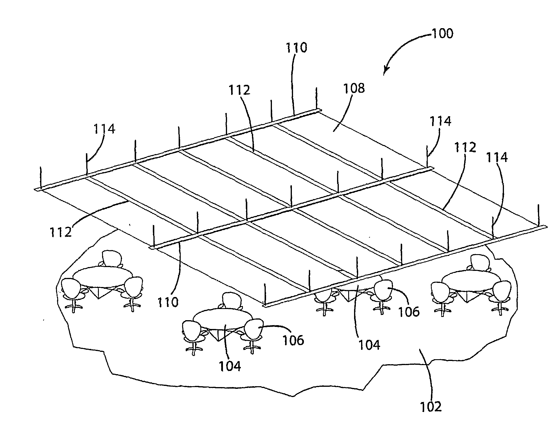
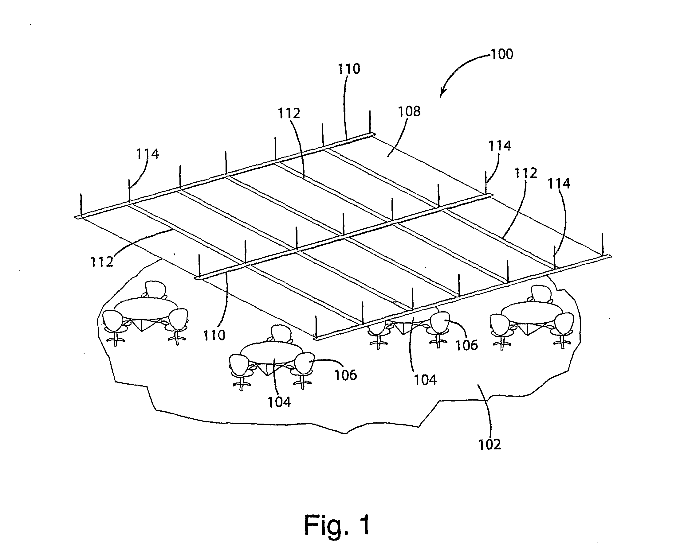
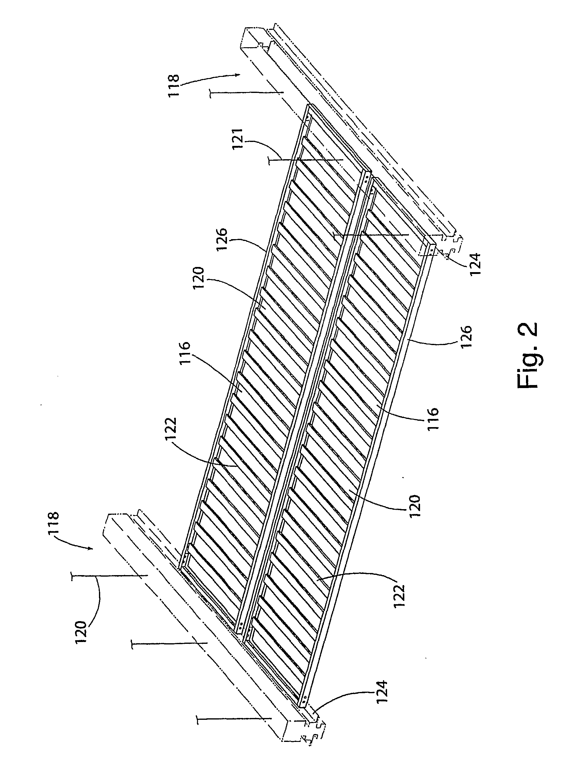
A LED ladder system (650) includes strip units (674) with spaced apart LED elements. Network connection configurations (810, 850, 856, 868) receive AC power and selectively apply DC power to the strip units (674) based on control signals. A concertina visual shield configuration (902) is positioned adjacent the ladder system (650) to affect visual lighting properties.

Description

CROSS-REFERENCE TO RELATED APPLICATIONS[0001]This application claims priority of U.S. Provisional Patent Application Ser. No. 60 / 606,019 filed Aug. 31, 2004.STATEMENT REGARDING FEDERALLY SPONSORED RESEARCH OR DEVELOPMENT[0002]Not applicable.REFERENCE TO A MICROFISHE APPENDIX[0003]Not applicable.BACKGROUND OF THE INVENTION[0004]1. Field of the Invention[0005]The invention relates to overhead structures for commercial interiors (i.e., commercial, industrial and office environments) requiring power and, more particularly, to a system of supported shields which permit the use of LED and other lighting elements with selectable materials surrounding the lighting elements in various configurations, and to: a ladder system for conveniently supporting LED or similar lighting elements; a network configuration for control of lighting schemes including color and intensity (as well as network control of other components such as sound, equipment, projection screens and the like); and particular v...

Claims


Application Information

Patent Timeline
IPC IPC(8): F21S8/04H05B37/02G05B11/32F21V21/03G05B15/02
CPCE04B9/32E04B9/366F21S2/00F21S4/003F21S10/00F21V23/0435F21V23/0442F21V27/00F21Y2101/02F21Y2103/003H01R25/147H05B33/0803H05B33/0857F21S4/20F21Y2103/10F21Y2115/10H05B45/00H05B45/20H05B45/37
Inventor SKIDMORE, MARSHAKENNEDY, SHEILAINSALACO, ROBERT W.LONG, JAMES B.HILLIS, W. DANIELHOWE, RUSSEL
Owner SKIDMORE MARSHA
Learn More