
Link Type Seismic Tie For Boilers

a technology of seismic tie and boiler, which is applied in the direction of machine supports, shock-proofing, light and heating apparatus, etc., can solve the problems of not being able to easily or accurately predict or control the design calculation, the ability of energy absorption means to be relatively ineffective, and the inability to enhance the plastic behavior of boilers. to achieve the effect of reducing the relative displacement between the boiler and its supporting structure, reducing the effect of seismic energy generation

Inactive Publication Date: 2008-11-06
THE BABCOCK & WILCOX CO
View PDF6 Cites 10 Cited by
  • Summary
  • Abstract
  • Description
  • Claims
  • Application Information

AI Technical Summary

Benefits of technology

[0014]It is an object of the present invention to provide a seismic tie that dissipates seismic energy in a boiler system more effectively than a straight-bar link-type tie and supplies more damping than a straight-bar link-type tie to restrain the relative displacement between boiler and its supporting structure.
[0016]It is a further object of the present invention to protect the boiler from overstresses. This would be especially so if the actual applied seismic force happens to be greater than the forecasted design force.
[0017]Finally, it is an object of the present invention to provide protection against boiler pressure past rupture and furnace rupture by supplying a connection that is more able than the pressure parts alone to absorb seismic force while deforming.
[0019]The finger plates include a diamond-shaped opening with rounded corners which increases the damping contribution provided by each finger plate. The shape of the opening gives the finger plate a varying cross section. The large pin at the buckstay of the boiler and the large pin at steel structural support includes a tapered cross section which increases the damping contribution provided by each pin. The shape of the large pins gives a varying cross section thus making the pin a so-called constant stress beam-type member.
[0020]The link type seismic tie of the present invention is designed to supply substantially more damping than a straight-bar link-type tie. Also, the seismic tie of the present invention accomplishes this in a more predictable manner because the plasticity in the bending of the finger plates is more predictable than the buckling and subsequent bending plasticity of a straight bar. Once a straight bar permanently kinks, it may be so severely misaligned that it does not provide any further restraint or damping. In addition to the usual dangers, an earthquake could be especially hazardous to boiler personnel for two reasons: pressure parts could burst, and hot combustion gas could be released if there is a furnace rupture. Therefore, the seismic tie of the present invention protects the boiler from overstresses, especially when the actual applied seismic force is greater than the forecasted design force. With respect to load-path, the seismic tie of the present invention is in series with the boiler's pressure parts, and therefore is in a position to provide protection against boiler pressure part rupture and furnace rupture by supplying a connection that is more able than the pressure parts alone to absorb seismic force while deforming.

Problems solved by technology

However, it is not practical to configure the boiler for enhanced plastic behavior.
The straight-bar link-type tie of the prior art provides only a very limited ability to dissipate seismic energy.
However, this means of energy absorption is relatively ineffective and not easily or accurately predicted or controlled by design calculations.
Also, unacceptably large boiler displacements may be necessary before any significant seismic energy would be absorbed.

Method used


Image

  • Link Type Seismic Tie For Boilers
  • Link Type Seismic Tie For Boilers
  • Link Type Seismic Tie For Boilers

Examples


Embodiment Construction

[0031]Referring now to the drawings, in which like reference numerals are used to refer to the same or similar elements, FIG. 3 shows a schematic view of the link type seismic tie 10 arranged between a steel structural support 30 and a boiler 1. The boiler 1 is hung by rods 50 from the top of the steel support 30.

[0032]As shown in greater detail in FIG. 4, the seismic tie 10 is shown arranged between a steel structural support 30 and a buckstay 40 of a boiler 1. Boiler buckstays are described in more detail in U.S. Pat. Nos. 3,277,870, 4,059,075, 5,207,184, 5,557,901, which are incorporated by reference.

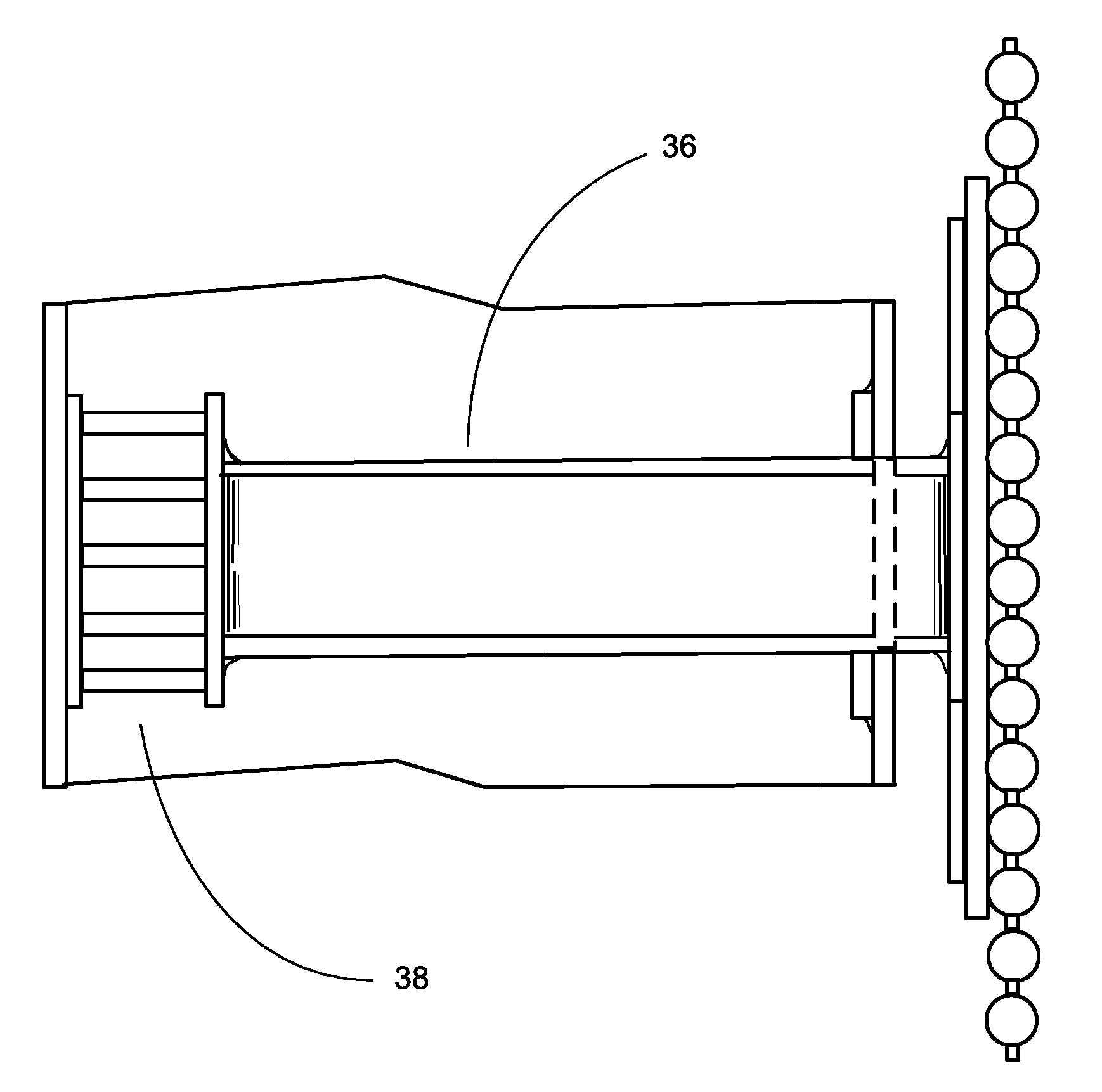
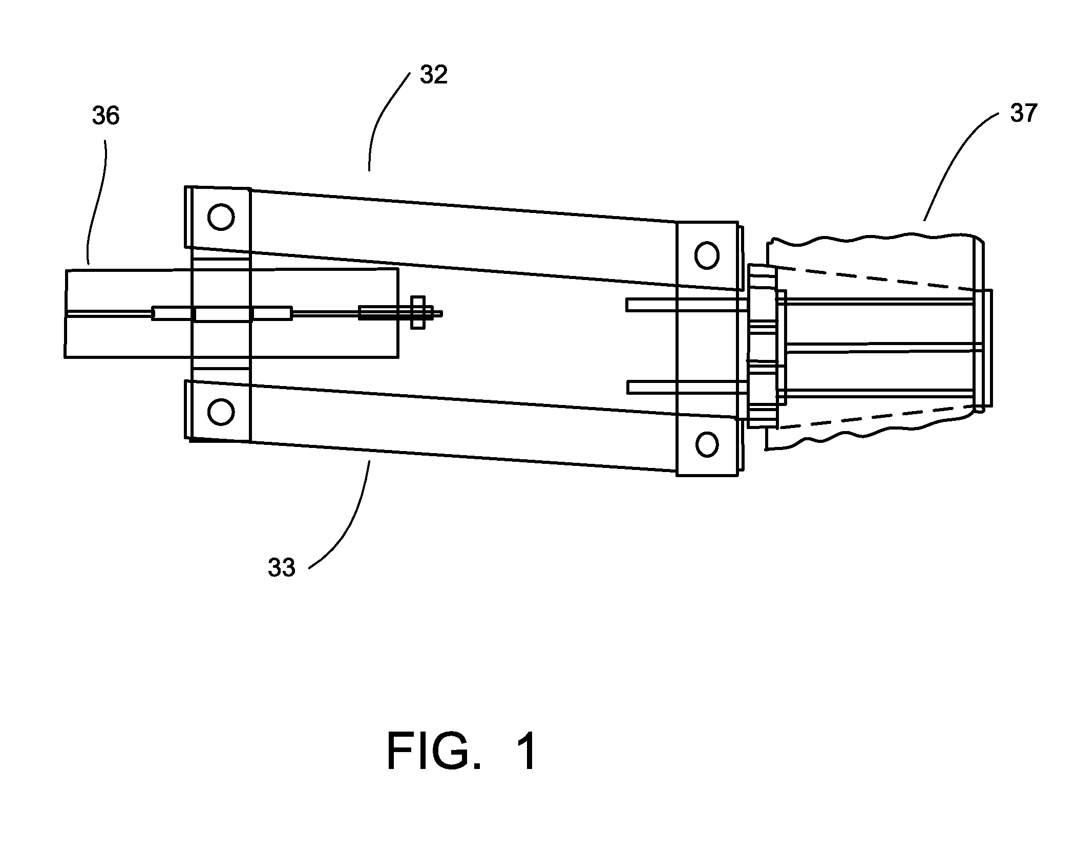
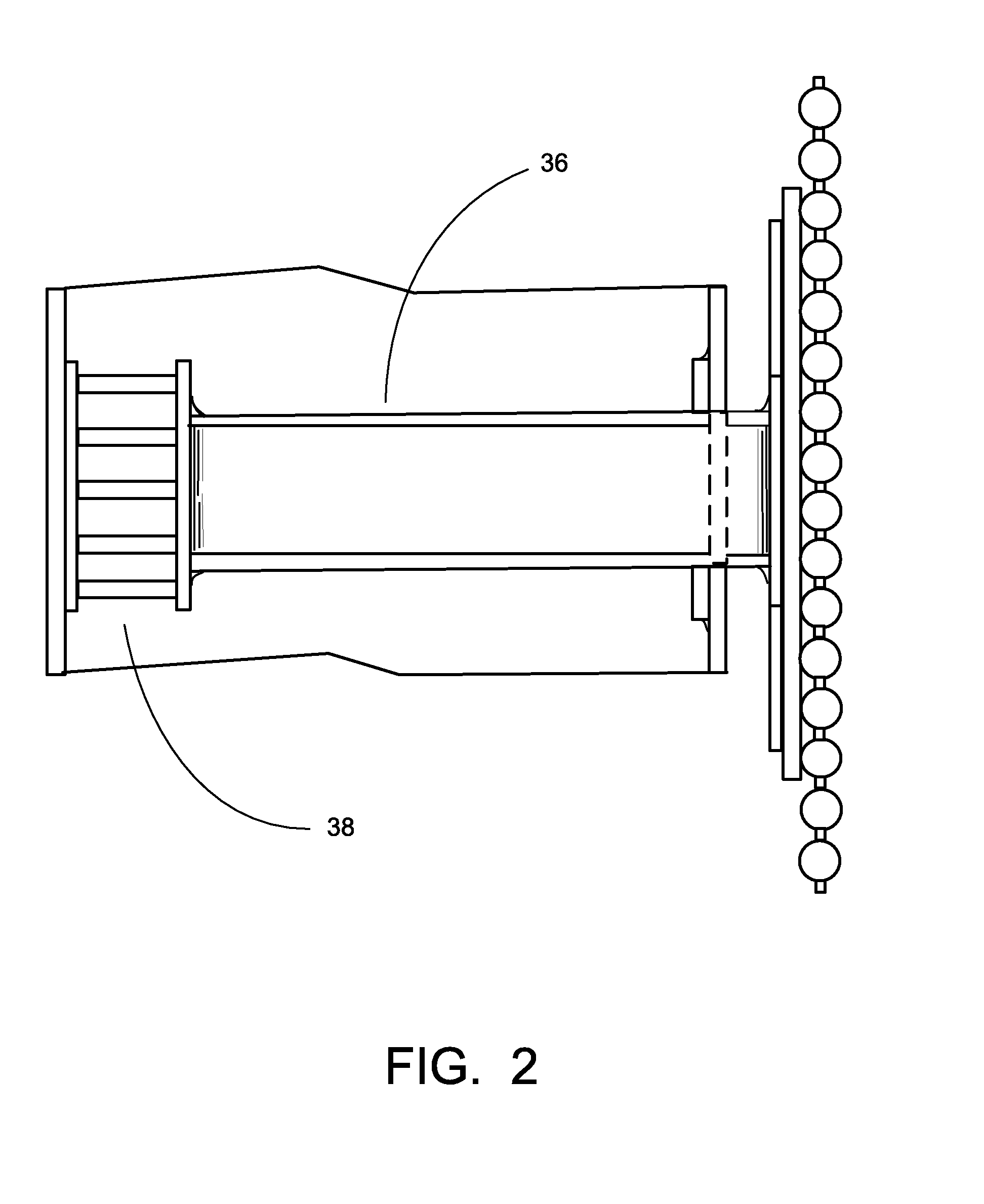
[0033]The seismic tie 10 comprises two horizontally arranged, parallel, and spaced apart link members 11, which are connected at their ends to large pins 24 and 26. As shown in greater detail in FIG. 5, each of the link members 11 include two horizontally arranged and parallel longitudinal outboard stringers 12 and a horizontally arranged and parallel longitudinal center stringer 14 ...


PUM


Abstract

A link-type seismic tie is provided between a steel structural support and a buckstay, and includes two horizontally arranged, parallel, and spaced apart link members, which are connected at their ends to large vertical pins. Each of the link members includes two horizontally arranged and parallel longitudinal outboard stringers and a horizontally arranged and parallel longitudinal center stringer centered between the two outboard stringers. Each link member further includes finger plates standing upright and spaced apart from each other relatively perpendicular to the longitudinal stringers. The finger plates are held between each of the outboard stringers and the longitudinal center stringer. A gusset plate connects the outboard stringers to a pin plate, which is connected to a large pin at the buckstay. The other end of the link members is connected to a large pin at the steel structural support via the ends of the outboard stringers.

Description

FIELD AND BACKGROUND OF INVENTION[0001]The present invention relates generally to the field of steam generators and in particular to a new and useful link type seismic tie for a boiler system for absorbing and dissipating seismic force or energy to limit the displacement of the boiler system, including support steel frames and piping.[0002]During an earthquake, seismic energy is dissipated by damping due to plastic behavior of the structural system. The structural system consists of the supporting structural steel, boiler ties, and the boiler itself. Using certain techniques, the structural steel may be designed to enhance damping by plastic behavior. However, it is not practical to configure the boiler for enhanced plastic behavior. This is because the boiler's overall configuration is governed by the pressure part design and arrangement.[0003]There are a variety of seismic ties currently available for dissipating seismic energy or forces. A typical link-type seismic tie is shown i...

Claims


Application Information

Patent Timeline
IPC IPC(8): F22B37/24
CPCF22B37/24
Inventor RADKE, EDWARD F.
Owner THE BABCOCK & WILCOX CO
Learn More