Four-Stroke Free Piston Engine

a free piston engine and four-stroke technology, applied in the direction of free piston engine, combustion engine, machine/engine, etc., can solve the problems of limiting the efficiency of four-stroke internal combustion engine, affecting the efficiency of four-stroke engine, and general inacceptability of pollution, so as to improve the access to lubricating and cooling, and to add any side loading

Inactive Publication Date: 2008-11-06
CHEESEMAN PETER CHARLES
View PDF2 Cites 56 Cited by
  • Summary
  • Abstract
  • Description
  • Claims
  • Application Information

AI Technical Summary

Benefits of technology

[0010]In accordance with the invention, a four-stroke free piston internal combustion engine utilizes a shuttle frame located external to combustion chambers to rigidly link the reciprocating movements of shuttle parts along a shuttle centerline. The shuttle frame replaces the conventional internal connecting rod located within the combustion chambers, thereby improving access for lubricating and cooling the shuttle parts without adding any side loading to the shuttle parts.

Problems solved by technology

However, standard crank operated, spark ignition (SI), four-stroke, internal combustion engines, such as those found commonly in cars, are limited to a compression ratio of roughly 10:1, because of “knocking” at higher compression ratios.
This limited compression ratio fundamentally limits the efficiency of an SI engine.
Unfortunately, the non-uniform mixing of fuel and air during fuel injection in a diesel engine typically creates particulate emissions (“soot”) as well as polluting gases, and this pollution is generally unacceptable, despite the higher efficiency.
This leads to wear on the bearing.
It also means that the piston spends a significant fraction of its cycle near TDC and so loses a significant amount of heat to the chamber walls, thus decreasing efficiency.
However, the practical difficulty of timing HCCI in synchrony with the piston at TDC in a crank engine has deterred the use of HCCI in crank operated internal combustion engines.
Two stroke engines suffer from the problem that there is inevitably some mixing of the fresh charge with the exhaust gas stream.
This not only leads to lower efficiency, but generally produces unacceptable levels of pollution.
This method of coupling has significant disadvantages.
Firstly, the pinions exert a strong side load on both pistons, because they necessarily act on the pistons' sides, rather than along the pistons' axes.
The main problems caused by side loading are increased wear and difficulties of lubricating under high load.
Another disadvantage of the rack and pinion coupling is the wear and friction on both the rack and the pinion, as all the force on the piston must be transmitted through this coupling.
Such complex couplings reduce the efficiency of the engine.

Method used


Image

  • Four-Stroke Free Piston Engine
  • Four-Stroke Free Piston Engine
  • Four-Stroke Free Piston Engine

Examples


first embodiment

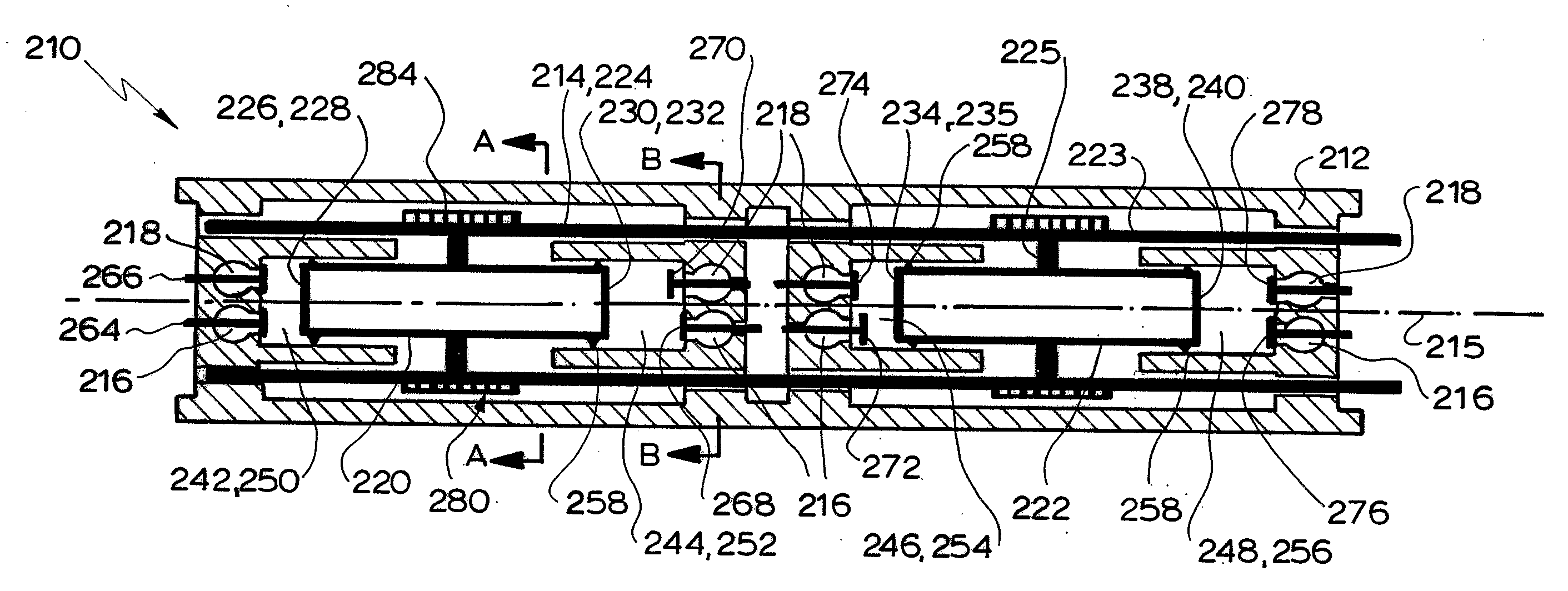
[0044]A first embodiment comprising a linear four stroke free piston internal combustion engine 210 is depicted in FIGS. 2A to 2C. The engine 210 comprises an engine block structure 212 and a rigid shuttle 214 mounted to the engine block structure 212 for reciprocal movement relative thereto along a linear shuttle centerline 215. The engine 210 further comprises a selectively sealable network of inlet passages 216, which communicate with a fuel / air supply (not shown), and a selectively sealable network of outlet passages 218, which communicate with an exhaust system (not shown).

[0045]The shuttle 214 comprises a generally cylindrical first shuttle part 220, a generally cylindrical second shuttle part 222 axially spaced from the first shuttle part 220 and a shuttle frame 224 rigidly fixing the first shuttle part 220 relative to the second shuttle part 222. Accordingly, the first and second shuttle parts 220, 222 cannot move relative to one another. The first and second shuttle parts 2...

second embodiment

[0051]Since the shuttle frame 224 is entirely external of the chambers 250, 252, 254, 256, the bore seals 162 and any associated lubrication of the example engine 110 are not necessary. Further, the chambers 250, 252, 254, 256 are all identical, unlike the example engine 110 in which the rod 124 compromises the second and third chambers 152, 154 and reduces the surface area of the second and third shuttle surfaces 132, 136 relative to the first and fourth shuttle surfaces 128, 140. This means that the second embodiment encounters less friction, has less components and has less possible gas leakage points. Further, since the shuttle parts 220, 222 are readily accessible from the outside, the shuttle parts 220, 222 can be easily cooled and lubricated. In contrast, it would be very difficult to deliver lubricating or cooling fluid to the shuttle parts 120, 122 of the example engine 110, without seriously compromising performance.

[0052]A second embodiment comprising a coaxial four strok...

third embodiment

[0059]A third embodiment comprising a toroidal four stroke free piston internal combustion engine 410 is depicted in FIGS. 4A to 4D. The engine 410 comprises an engine block structure 412 and a rigid shuttle 414 mounted to the engine block structure 412 for reciprocal movement relative thereto along a circular shuttle centerline 415. The shuttle 414 is also pivotally mounted on a central shaft 492 via spokes 484. The engine 410 further comprises a selectively sealable network of inlet passages 416, which communicate with a fuel / air supply (not shown), and a selectively sealable network of outlet passages 418, which communicate with an exhaust system (not shown).

[0060]The shuttle 414 comprises a first shuttle part 420 in the general shape of a toroidal sector, a second shuttle part 422 in the general shape of a toroidal sector and a shuttle frame 424 rigidly fixing the first shuttle part 420 relative to the second shuttle part 422. Accordingly, the first and second shuttle parts 420,...


PUM


Abstract

A free piston engine utilizes a shuttle frame external to combustion chambers to rigidly link shuttle parts reciprocating along a centerline. If the shuttle parts are spaced apart along the centerline, the shuttle frame may be struts extending from the shuttle parts and linked by rods. Alternatively the shuttle parts are within a tubular shuttle frame that forms part of the combustion chamber boundary. If one shuttle part is arranged around the other with both centered about the centerline, the shuttle frame may include an annular plate between a cylindrical inner shuttle part and an annular outer shuttle part. Alternatively the shuttle frame may include an inner tube with a cylindrical inner shuttle part within the inner tube, and an outer tube with an annular outer shuttle part arranged between the inner and the outer tubes so that the shuttle frame forms part of the combustion chamber boundary.

Description

FIELD OF INVENTION[0001]The present invention relates to free piston engines and more specifically to a four-stroke free piston engine.BACKGROUND OF THE INVENTION[0002]Otto cycle four-stroke internal combustion engines have been in use for over a century, and are still widespread. This is mainly because of their relatively high efficiency and high power-to-weight ratio.[0003]However, standard crank operated, spark ignition (SI), four-stroke, internal combustion engines, such as those found commonly in cars, are limited to a compression ratio of roughly 10:1, because of “knocking” at higher compression ratios. This limited compression ratio fundamentally limits the efficiency of an SI engine.[0004]A diesel engine, on the other hand, is not subject to knocking because the fuel is not injected until near maximum compression is achieved. As a result, diesel engines can achieve a higher compression ratio than SI engines, and therefore higher efficiency. Unfortunately, the non-uniform mix...

Claims


Application Information

Patent Timeline
Patent Type & Authority Applications(United States)
IPC IPC(8): F02B71/00
CPCF02B53/02F02B63/04F02B63/041F02B71/00F02B71/04F02B2075/027Y02T10/17Y02T10/12
Inventor CHEESEMAN, PETER CHARLES
Owner CHEESEMAN PETER CHARLES
Why Eureka
Try Eureka