
Cleaning method, particle removing method, cleaning apparatus, and cleaning liquid

a cleaning method and particle removal technology, applied in the direction of cleaning using liquids, instruments, photomechanical equipment, etc., can solve the problems of insufficient effect, difficult to meet such strict requirements with conventional physical cleaning or chemical cleaning described above, and increasing particle requirements in the futur

Inactive Publication Date: 2008-11-06
HOYA CORP
View PDF12 Cites 3 Cited by
  • Summary
  • Abstract
  • Description
  • Claims
  • Application Information

AI Technical Summary

Benefits of technology

The method allows for the effective removal of particles from photomasks without damaging the fine patterns, even in undercut areas, improving cleaning efficiency and preventing re-adhesion, while being adaptable to various particle types and surface conditions.

Problems solved by technology

In addition, in association with shortening of the wavelength of exposure light, requirements for particles will be increasingly strict in the future.
However, it is revealed that fulfillment of such strict requirements with the conventional physical cleaning or the chemical cleaning described above is very difficult.
In other words, although countermeasures such as increasing the number of times of cleaning have been taken in order to fulfill the above-described requirements, sufficient effect has not been achieved.
In addition, in association with the microminiaturization of the patterned portion formed on the photomask, flow of cleaning liquid can hardly be established at the light-transmitting portion between the patterns.
From this reason as well, cleaning effect cannot be achieved.
Therefore, problem involved therein is that the APM cleaning which is used for cleaning the photomask cannot be continued for a long time.
However, there is a problem that exposure light is disturbed (such as scattering and absorption) during using the photomask, and therefore the particle of the undercut portion also needs removing.
However, it is difficult to remove this foreign substance only with the conventional cleaning method in the related art, and in addition, there is a problem such that an overhung mask pattern may be destroyed, resulting in producing an inferior quality when the high-pressure water cleaning or the ultrasonic wave cleaning, which is the physical cleaning, is employed.

Method used


Image

  • Cleaning method, particle removing method, cleaning apparatus, and cleaning liquid
  • Cleaning method, particle removing method, cleaning apparatus, and cleaning liquid
  • Cleaning method, particle removing method, cleaning apparatus, and cleaning liquid

Examples


example 1

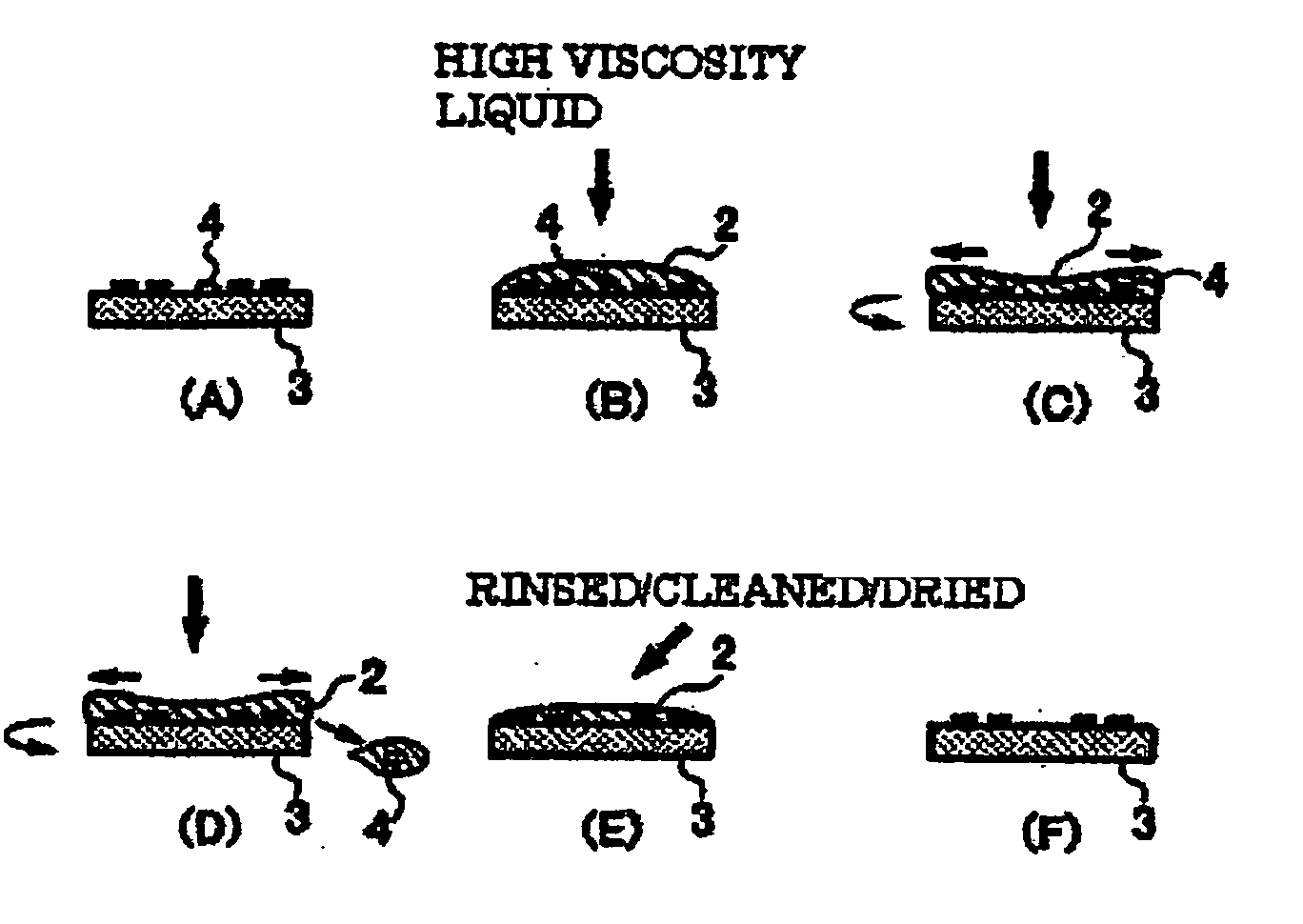
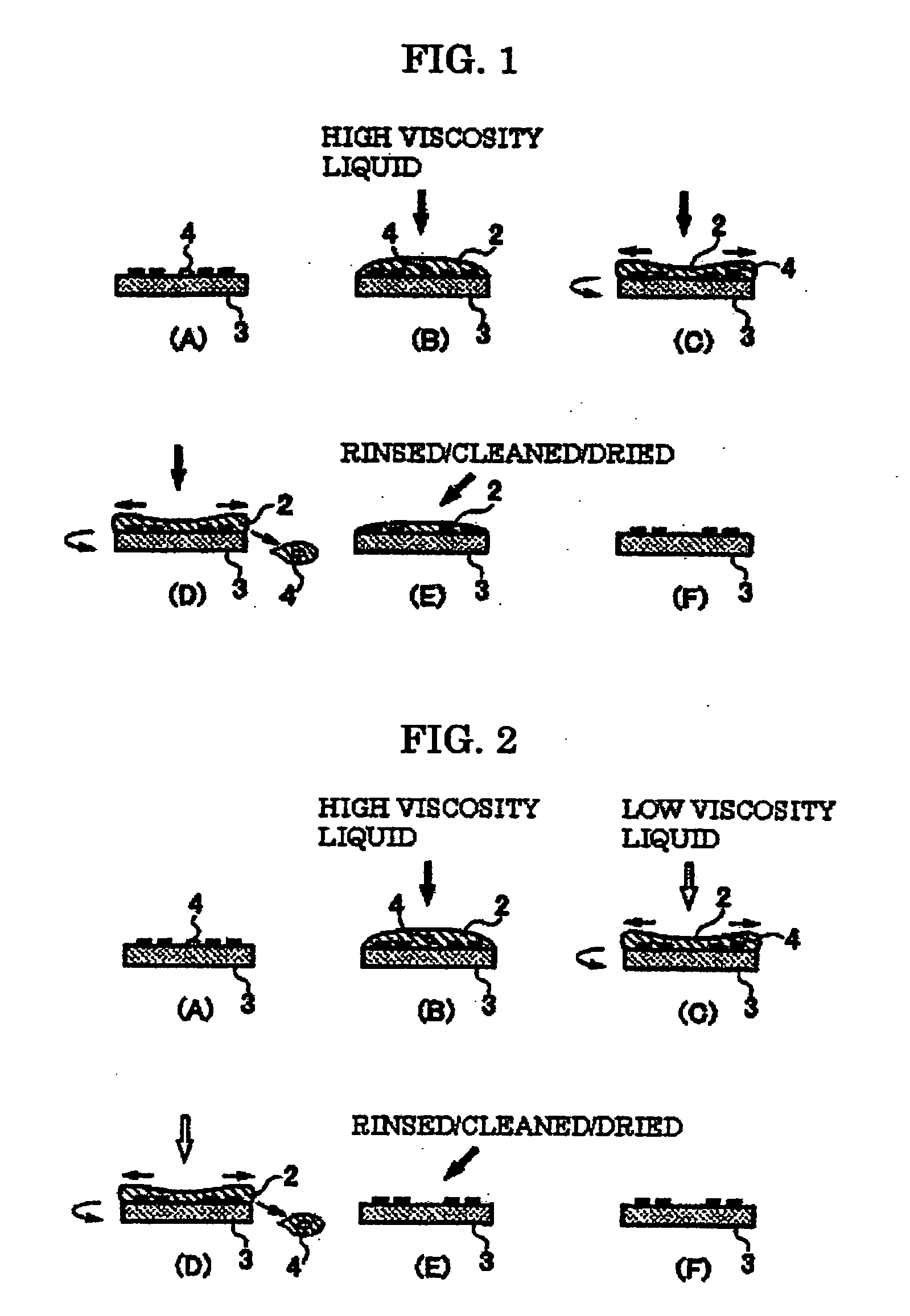
[0092]FIG. 1 is an explanatory view illustrating a particle removing method according to an example 1 of the present invention. Referring now to FIG. 1, the particle removing method according to the example 1 will be described. In the particle removing method according to the example 1, a photomask 3 to be cleaned is installed on an object holding part (not shown) which fixes and rotates the photomask 3 by a vacuum adsorption device or the like (FIG. 1A), and by a liquid supply part, a high viscosity liquid 2 is supplied to an upper surface of the photomask 3 to be cleaned using a dripping nozzle (not shown) (FIG. 1B).

[0093]Then, the photomask 3 is rotated while supplying the high viscosity liquid 2. By rotating the photomask 3 in this manner, the high viscosity liquid 2 moves by a centrifugal force (FIG. 1C). A rotating speed at this time was set to the speed capable of relatively moving the liquid efficiently with respect to the photomask (approx. 200 rpm). While the high viscosit...

example 2

[0098]FIG. 2 is an explanatory view illustrating the particle removing method according to an example 2 of the present invention. Referring now to FIG. 2, the particle removing method according to the example 2 will be described hereafter. In the particle removing method according to the example 2, the photomask 3 to be cleaned is installed on the object holding part (not shown) which fixes and rotates the photomask 3 by the vacuum adsorption device or the like (FIG. 2A), and then, the high viscosity liquid 2 which is the same liquid as that used in the example 1 is supplied to the cleaning surface of the photomask 3 through the liquid supply part such as the dripping nozzle or the like, not shown (FIG. 2B). In this case, vibrations of the ultrasonic wave may be applied to the object by an ultrasonic wave generating device, not shown. Subsequently, the high viscosity liquid 2 is moved by injecting a lower viscosity liquid than the high viscosity liquid such as pure rinsing water at ...

example 3

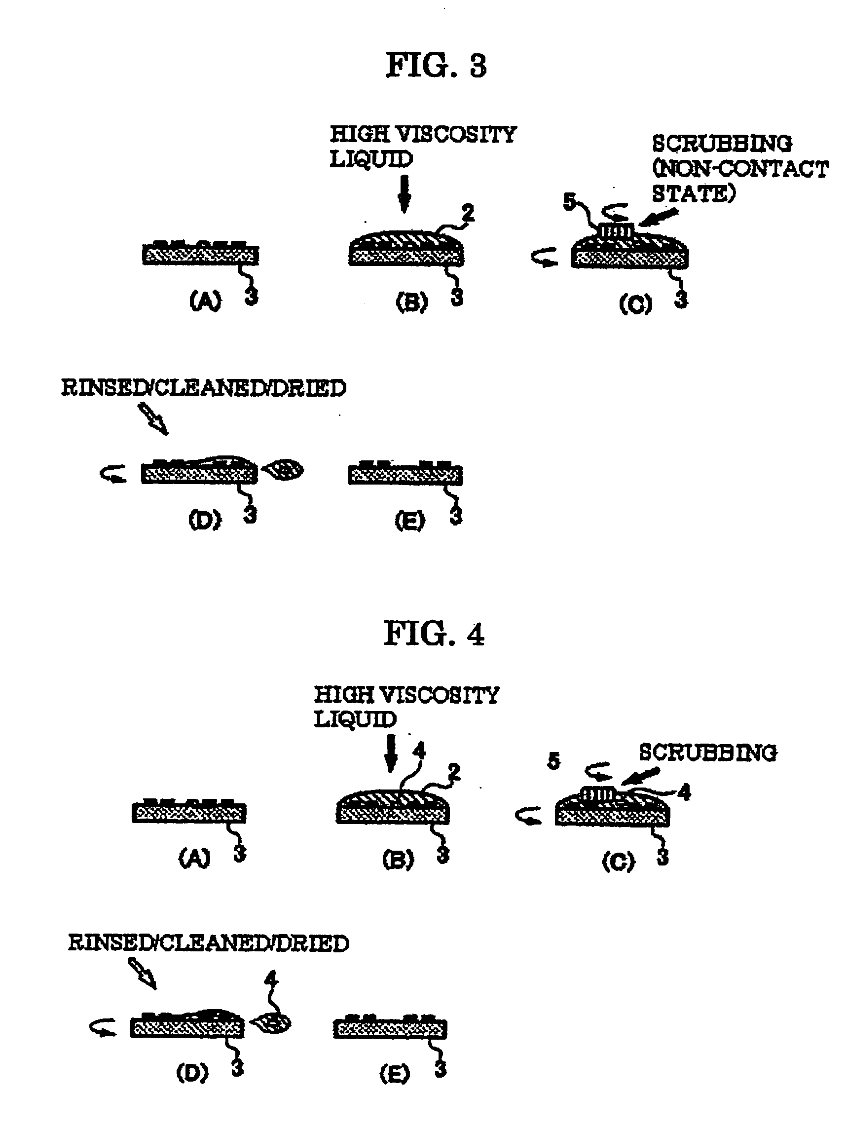
[0105]FIG. 3 is an explanatory view illustrating the particle removing method according to an example 3 of the present invention. Referring now to FIG. 3, the particle removing method in the example 3 will be described. In the particle removing method according to the example 3, the photomask 3 to be cleaned is installed on the object holding part (not shown) which can perform rotating operation (FIG. 3A), and the same high viscosity liquid 2 as that used in the example 1 and the example 2 is supplied to the surface of the photomask to be cleaned by the liquid supply part using the dripping nozzle (not shown) (FIG. 3B).

[0106]Subsequently, a gap (ex. approx. 1 mm) is provided between the photomask 3 and a sponge 5 (such as a circular sponge formed of PVA having diameter of 5 cm), and the sponge 5 is moved (ex. 100 mm / sec.) by an arm (not shown) for holding the sponge on the photomask 3 while keeping a non-contact state by keeping the aforementioned gap, whereby the entire surface of ...


PUM

PropertyMeasurementUnit
pHaaaaaaaaaa
viscosityaaaaaaaaaa
sizeaaaaaaaaaa

Abstract

The present invention provides a mechanism capable of removing a minute particle adhered to a fine pattern or the like without giving damages to the pattern or the like. After being installed on a device which can perform rotating operation, the high viscosity liquid is dropped on an upper surface of an object such as a photomask to be cleaned by a liquid supply part, and then the photomask is rotated to move the high viscosity liquid. During the movement of the high viscosity liquid, a particle adhered to the object such as the photomask is contained in the high viscosity liquid, and is removed. Further, the particle thus contained in the liquid is prevented from re-adhering to the object such as the photomask by controlling a zeta potential of the high viscosity liquid, and is removed from the object such as the photomask.

Description

[0001]This is a Continuation of application Ser. No. 10 / 551,135 filed Nov. 1, 2005, which in turn is a National Phase of Application No. PCT / JP2004 / 004634, filed Mar. 31, 2004, which claims the benefit of Japanese Patent Application No. 2003-097092 filed Mar. 31, 2003. The disclosure of the prior applications is hereby incorporated by reference herein in its entirety.TECHNICAL FIELD [0002]The present invention relates to a cleaning method, a particle removing method, a cleaning apparatus and cleaning liquid for removing particles such as dirt adhered to an object such as a photomask or a semiconductor wafer.BACKGROUND ART [0003]For example, if a particle is adhered to a photomask that is used as a mask for fine pattern transfer, which is required when manufacturing semiconductor device such as an LSI or a liquid crystal panel, the particle is transferred as a defect. Therefore, when manufacturing the photomask, a cleaning process for removing the particle is provided as one of impor...

Claims


Application Information

Patent Timeline
Patent Type & Authority Applications(United States)
IPC IPC(8): B08B3/10B08B3/04G03F7/42B08B3/08B08B3/02B08B7/00C11D11/00G03F1/82H01L21/304H01L21/306
CPCB08B7/0014C11D11/0047H01L21/02052G03F1/82C11D11/0058C11D2111/42C11D2111/22H01L21/6715
Inventor TAKUSHIMA, KATSUHIRO
Owner HOYA CORP
Learn More