Heated Coupling

a technology of electric heating and couplings, applied in the direction of pipe heating/cooling, machine/engine, service pipe systems, etc., can solve the problems of delayed heating, affecting the functional properties of liquids, and inability to use anti-freez

Active Publication Date: 2008-11-06
VOLVO LASTVAGNAR AB
View PDF16 Cites 41 Cited by
  • Summary
  • Abstract
  • Description
  • Claims
  • Application Information

AI Technical Summary

Benefits of technology

[0036]As an alternative to the clip-on device, the heating device may be integrated in the hose connector. This is a more expensive arrangement, as a standard hose connector can not be used. On the other hand, the through-connection of the electric cable may not require a recess through the end seal, as described above. Instead the end seal can be integrated in the hose connector, whereby a pair of electrical leads or a plug-in socket can be provided in the end surface facing the fluid hose. This solution may also require additional protection and/insulation during cold weather conditions.
[0037]As stated above, it is desirable to provide an electrically heated fluid hose with at least one hose connector having an electrically heated device that may be arranged to heat at least part of the hose connector. A common feature for all embodiments is that the heated device should be located in close proximity to, or even in contact with, the hose connector to b...

Problems solved by technology

In other cases the use of anti-freeze is not possible, as this can affect the functional properties of the liquid.
This means that the heating is delayed until the engine has warmed up and that a number of extra hoses and connections are required for conveying water to multiple locations around the vehicle.
This solution is both expensive and unnecessarily complicated.
A problem with such known solutions is that heating is only provided for the hose itself.
Providing an ADR-classified vehicle with a fluid hose that is heated electrically is a difficult problem.
A disadvantage is that such a solution can cause leakage at the connection points...

Method used


Image

  • Heated Coupling
  • Heated Coupling
  • Heated Coupling

Examples


second embodiment

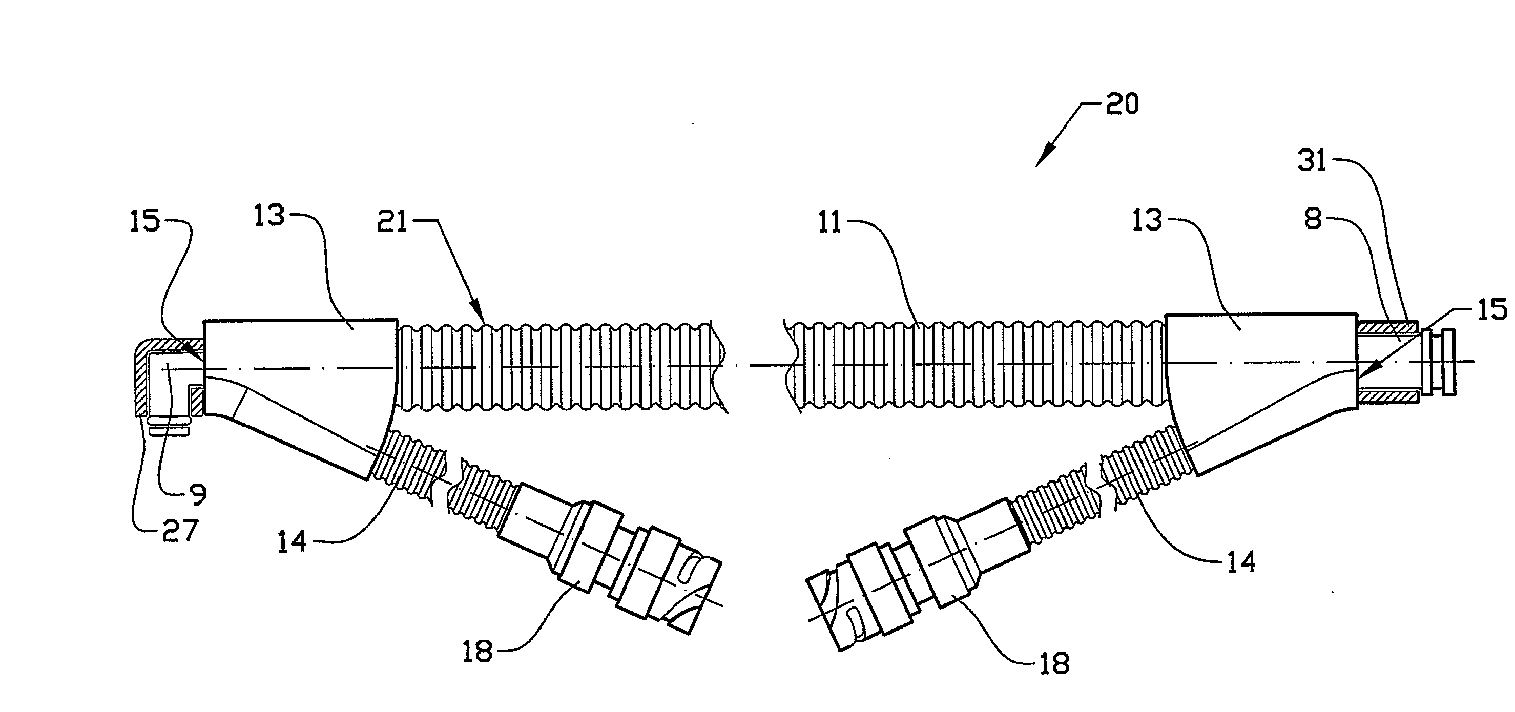
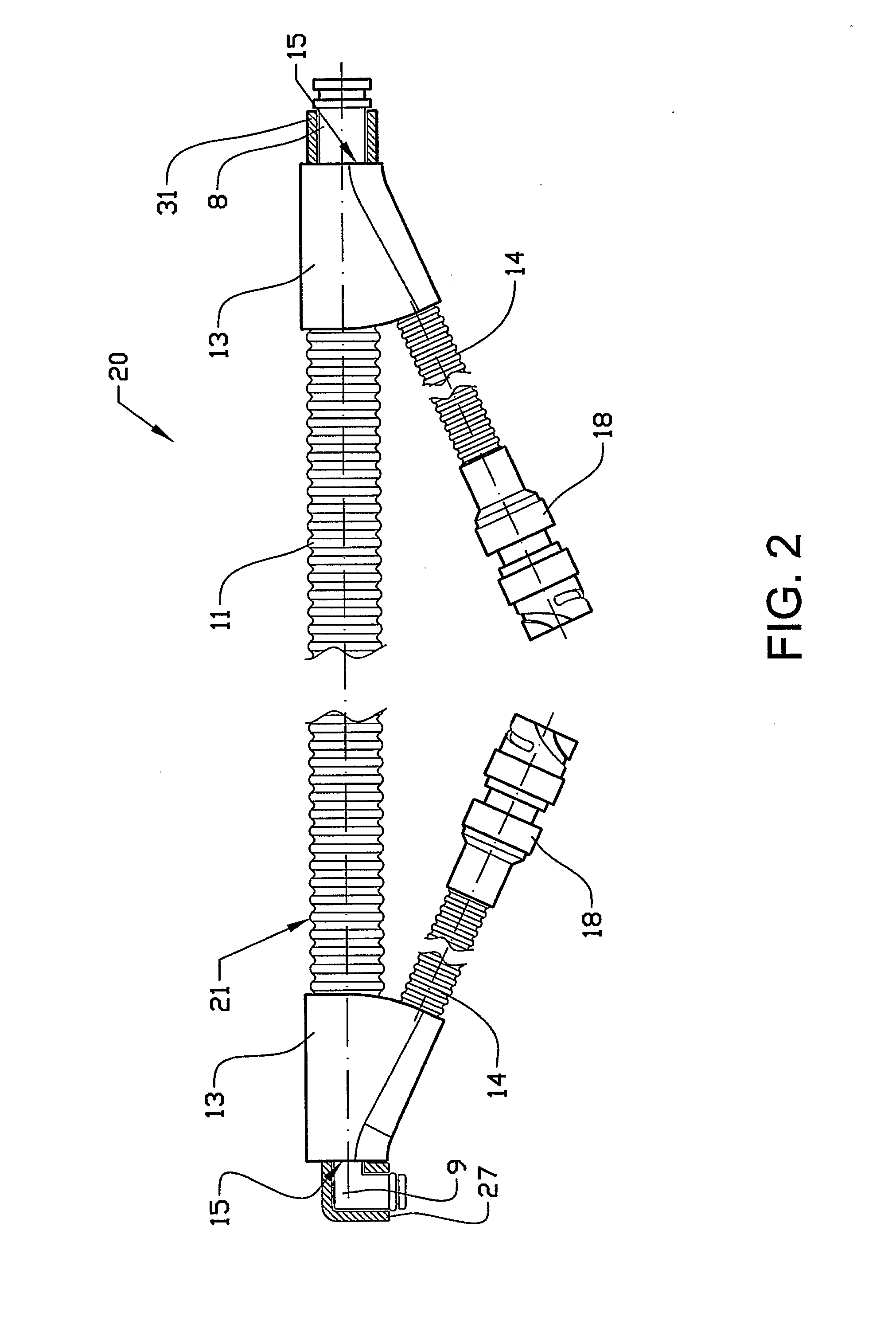
[0051]the invention is shown in FIG. 2. This figure shows a cabling 20 comprising substantially the same basic components as the cabling in FIG. 1, which components have retained the same reference numerals. The cabling 20 is not shown sectioned, whereby the enclosed components can not be seen. The cabling 20 comprises a fluid hose 2 having an integrated heated cable 3 for heating the fluid hose 2. The fluid hose 2 and the heated cable 3 are enclosed in a protective sheath 21. In this example the heated cable 3 is detached from the fluid hose 2 at both ends of the hose so that the respective ends of the cable 3 can be conducted to their respective electrical connector 18. The fluid hose 2 is provided with hose connectors 8 and 9 attached to the hose by means of clamping sleeves. The hose connector 8 and 9 respectively comprise a straight and an angled hose connector, arranged to be connected to a co-operating connector.

[0052]The protective sheath 21 of the cabling 20 comprises, as d...

third embodiment

[0056]FIG. 3 shows a cross-section of a cabling according to the invention. The cabling comprises a fluid hose 32 with an integrated heated cable 33 heating the fluid hose 32. The fluid hose 32 and the heated cable 33 are enclosed in a protective sheath 37. In this example the heated cable 33 comprises two electrical leads 33a, 33b which have been connected to leads embedded in the mantle of the fluid hose 32. Near a first end section 34 of the cabling the heated cable has been detached from the fluid hose, allowing the leads to be conducted to an electrical connector 36. At a second end section of the cabling the heated cable 33 has been detached from the fluid hose 32, allowing the leads 33a, 33b to be joined to form a closed circuit (not shown). At the first end section 34 of the cabling a hose connector 39 is inserted into and connected to the fluid hose 32.

[0057]The cabling further comprises a manifold 38 and a second corrugated plastic tube 40 for conducting the leads 33a, 33b...


PUM


Abstract

Cabling for a motor vehicle includes at least one fluid hose, a first cable for heating the fluid hose and at least one electrical connector for connecting the cable to an electrical supply, and at least one hose connector for connecting the fluid hose to a cooperating connector means. The hose connector may be provided with an electrically heated device arranged to heat at least part of the hose connector.

Description

BACKGROUND AND SUMMARY[0001]The invention relates to electrically heated couplings, in particular couplings for cabling used in a vehicle.[0002]A vehicle contains various types of containers or tanks containing liquids used for different purposes in the vehicle. There is often a need for maintaining such fluids above a certain temperature to ensure that the equipment using the fluid may be operated as intended. In some cases it is sufficient to add an anti-freeze to the liquid to prevent the liquid from freezing. In other cases the use of anti-freeze is not possible, as this can affect the functional properties of the liquid. In the latter cases the container or tank can be provided with a suitable heating device for melting the liquid if it freezes. The heating device can be activated before or during starting of the vehicle, depending on the ambient temperature and the volume of liquid to be melted. To ensure proper function of a system containing the liquid, hoses or cabling conv...

Claims


Application Information

Patent Timeline
IPC IPC(8): F16L53/00F16L53/38
CPCF01N2610/02F01N2610/10H05B3/58F16L53/008H01R13/005F01N2610/14F16L53/38
Inventor SONDEREGGER, SIGURDHENSTROM, BENGT
Owner VOLVO LASTVAGNAR AB
Why Eureka
Try Eureka