Apparatus and Methods for Inserting an Implant

a technology for implanting and disorienting the body, applied in the field of interbody distraction and implant/transplant insertion, can solve the problems of affecting the implantation process, affecting the insertion process, so as to achieve the effect of convenient removal and convenient removal

Active Publication Date: 2008-11-06
K2M
View PDF48 Cites 220 Cited by
  • Summary
  • Abstract
  • Description
  • Claims
  • Application Information

AI Technical Summary

Benefits of technology

[0021]In one or more embodiments, once the implant is suitably advanced into the distraction space between the adjacent spinal vertebrae, the ramps may be positioned such that the tang portion of the ramps may be adjacent to the implant, with no portion of the ramps being located between the implant and the vertebral bodies. However, at this stage, the compressive force from the vertebral bodies may still be supported by the ramps and the distraction guides. The tube member may then be retracted into a proximal position by suitably rotating the knob, thereby allowing the arm members to slide laterally outward, which may thereby release the implant from the clamp jaws. As the distraction guides move laterally outward along with the arm members, the angled faces of the ramps may slide down the angled surface of the outwardly moving distraction guides, thereby decreasing the combined height of the ramps until the vertebrae-contacting surfaces of the ramps are separated by a distance that is less than the thickness of the implant. This movement may gradually transfer the compressive force urging the adjacent vertebral bodies together from the ramp tips to the implant. In one or more embodiments, the transfer of the compressive load off the ramps may be operable to enable the ramps to be easily removed from the intervertebral cavity without disturbing the placement or positioning of the implant. Additionally, with the load removed from the distraction guide, and therefore the inserter, the inserter can also be easily removed.

Problems solved by technology

Notwithstanding this success, a variety of problems arise in connection with surgical interbody implant placement.
Surgeons can have difficulty with the implantation process because of individual pathology, deformity, anatomical space restraints, or implant material limitations.
Often, implant placement proves a difficult and time-consuming procedure when the adjacent vertebrae's soft tissue support elements degenerate, causing collapse of the spaces between the vertebrae.
This degenerative condition coupled with compromised adjacent tissues, nerves and vasculature may impede physical and visual access to the intervertebral space.
This distraction procedure has traditionally required the use of several surgical distraction instruments, which may increase the procedure's overall complexity, intensify the invasiveness of the surgical procedure, and possibly lead to iatrogenic vascular and neurosurgical injuries which can cause intraoperative surgical complications.
At the same time, use of multiple instruments may limit the surgeon's manual access and clear visualization of the involved intervertebral space.
This hammering technique vectors enormous shear forces through the spacer.
The actual implants have material and engineering limitations which may cause the implant to fracture, shear, or break apart as a result of these forceful insertion moments.
In addition, some implant designs require materials which do not tolerate well the use of impaction-type forces necessary to advance the implant into the intervertebral space.
While such implant insertion instruments provide a significant improvement in the art, the implant is not always safeguarded against substantial and potentially undesirable compression and shear forces during such advancing displacement between the pivoting distraction levers.
In addition, these instruments have not provided a simple mechanism for quickly and easily retracting the distal end tips of the levers from the distraction space following intervertebral placement of the implant.
Moreover, these instruments have not provided or contemplated the capability for use with implants of different sizes, such as implants having different height dimensions which may be indicated by specific patient requirements, without altering the insertion angle of the distal end tips of the distraction levers.
In this regard, an amplified increase in the tip insertion angle, associated with implantation of a significantly taller implant, can undesirably increase the complexity and difficulty of the surgical implantation procedure.

Method used


Image

  • Apparatus and Methods for Inserting an Implant
  • Apparatus and Methods for Inserting an Implant
  • Apparatus and Methods for Inserting an Implant

Examples


Embodiment Construction

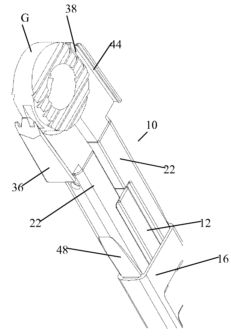
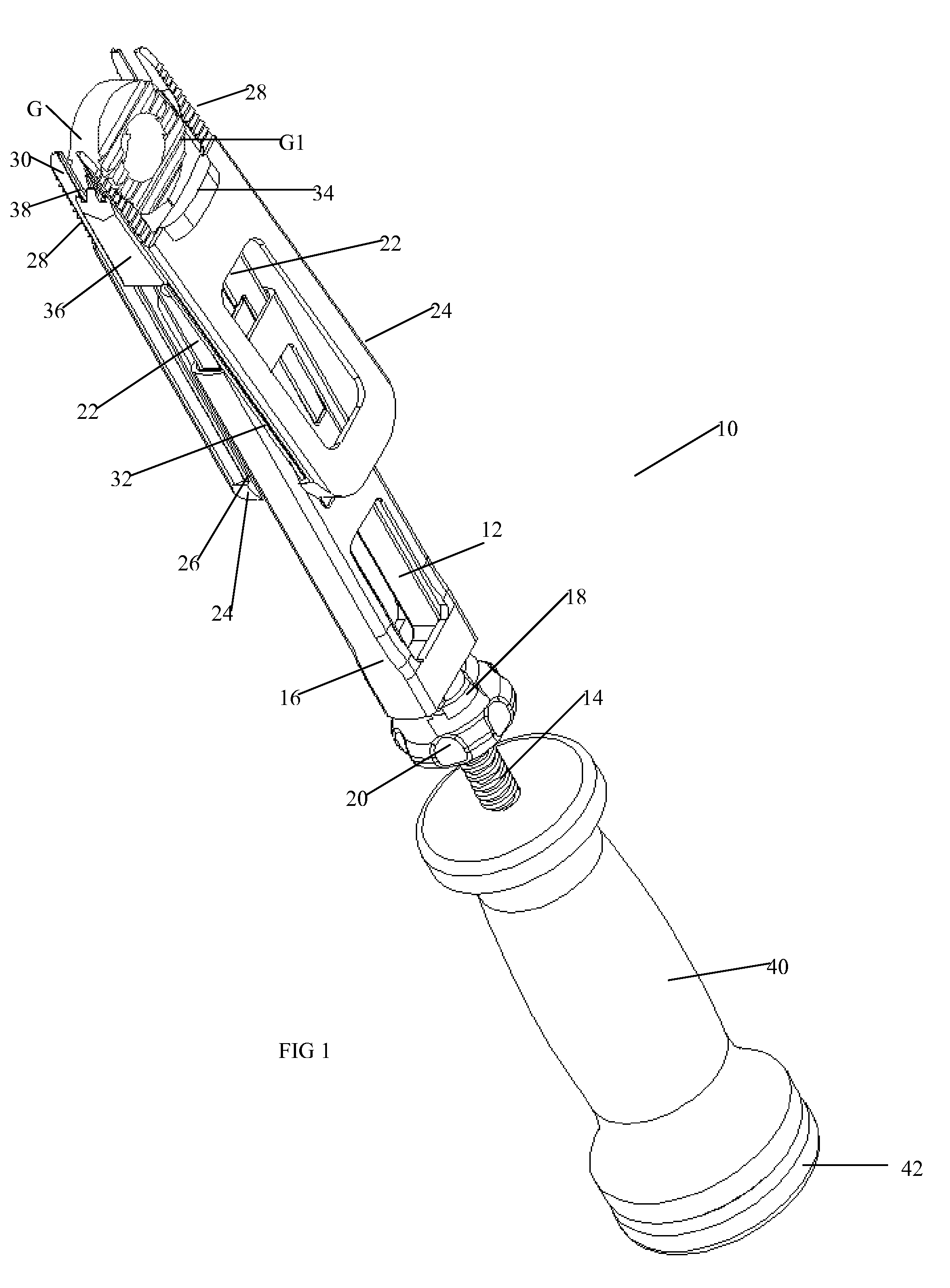
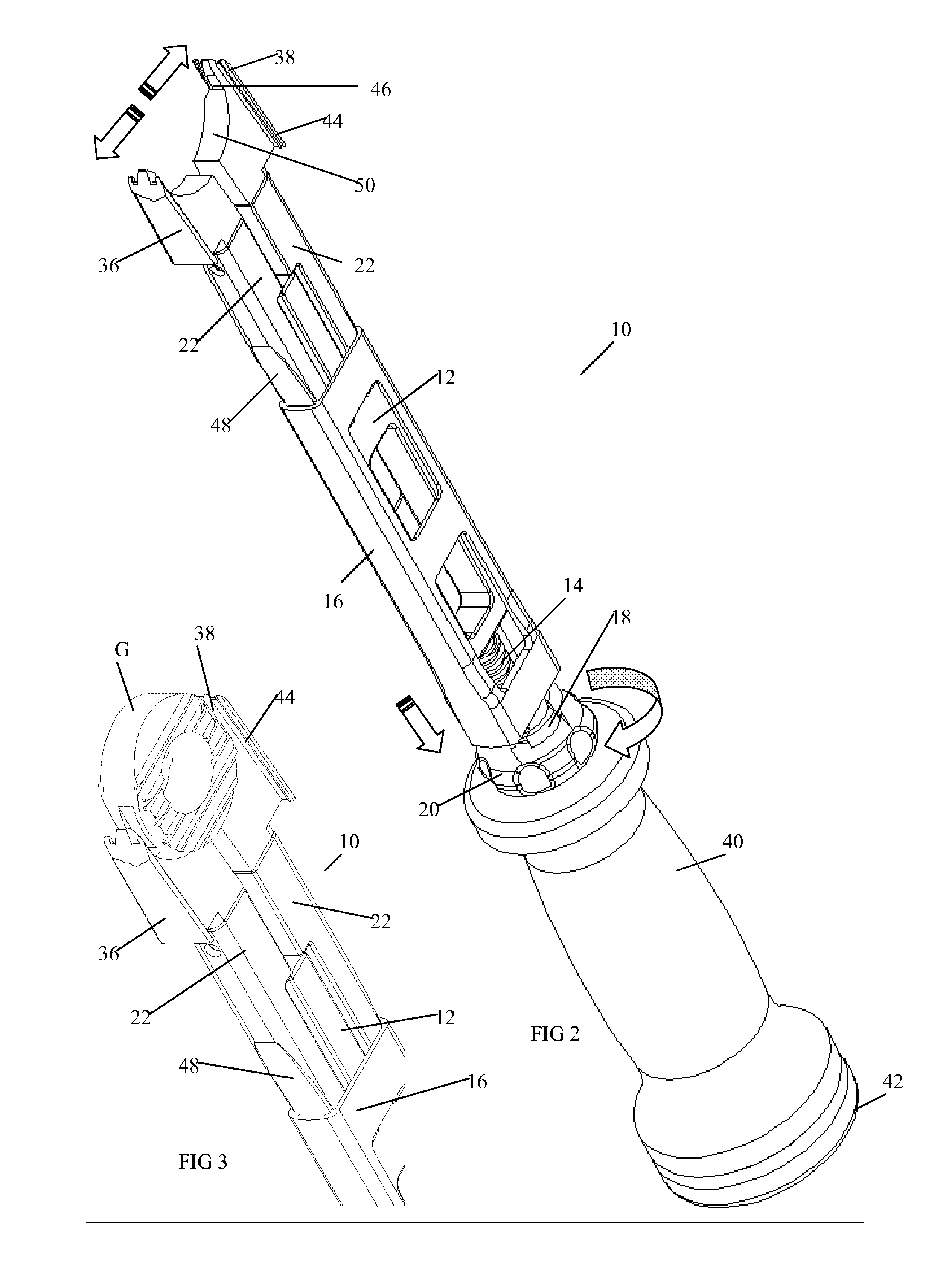
[0051]FIG. 1 is a right side perspective view of an intervertebral implant insertion instrument 10 for use in distracting adjacent bony structures such as adjacent spinal vertebrae V1 and V2, and / or for inserting an implant G and / or transplant of selected size and shape therebetween, in accordance with one or more embodiments of the present invention.

[0052]In one or more embodiments, the insertion instrument 10 and related implant G may be adapted for use in spinal surgical procedures for placement of the implant G into a distracted intervertebral space wherein the implant G may subsequently serve as a load bearing spacer element for maintaining a prescribed spacing between adjacent vertebral structures (or “vertebrae”) V1 and V2. In this regard, the implant G may be formed from a relatively sturdy and biocompatible material such as (but not limited to) a selected metal or metal alloy, bone, polymer, carbon fiber-reinforced polymer and / or ceramic. The implant G may be formed with a ...


PUM


Abstract

A system and method for inserting an implant into a cavity is disclosed, which may include advancing an implant insertion instrument toward a pair of adjacent bodies, the implant insertion instrument having two opposed ramps, wherein each ramp has a distal tip and wherein the longitudinal axes of the opposed ramps are separated by an initial angle; inserting the distal tips of the opposed ramps between the adjacent bodies, thereby creating an initial interbody cavity between the adjacent bodies; expanding the interbody cavity while maintaining the initial angle between the longitudinal axes of the opposed ramps; placing the implant in a final location between the adjacent bodies; transferring a compressive force urging the adjacent bodies together from the opposed ramps to the implant; and extracting the implant insertion instrument from the interbody cavity.

Description

CROSS REFERENCE TO RELATED APPLICATIONS[0001]This application claims the benefit of U.S. Provisional Patent Application No. 60 / 822,613 filed Aug. 16, 2006, the entire disclosure of which is hereby incorporated by reference.BACKGROUND OF THE INVENTION[0002]This present invention is directed to methods and apparatus for interbody distraction and implant / transplant insertion.[0003]The spine surgical community and surgical literature accept intervertebral devices (commonly known as interbody spacers, and allograft transplants) as part of the art and routine practice in the reconstruction of collapsed intervertebral disc spaces. Surgeons insert these interbody devices / transplants to facilitate bone fusion in between and into the contiguous involved vertebrae. This fusion creates a new solid bone mass, which acts to hold the spinal segment at an appropriate biomechanically restored height as well as to stop motion in a painful segment of the spine. Items surgically placed in these involve...

Claims


Application Information

Patent Timeline
Patent Type & Authority Applications(United States)
IPC IPC(8): A61B17/88
CPCA61B17/025A61F2/4611A61F2002/30892A61F2/442A61F2002/4627A61F2002/4628A61F2002/4475A61F2002/30593
Inventor BERRY, BRET M.GUYER, RICHARD D.ZIGLER, JACK E.PIKE, ADAM A.LEE, RANDALL F.
Owner K2M
Why Eureka
Try Eureka