Discrete variable geometry compressor

a compressor and variable geometry technology, applied in the direction of machines/engines, mechanical equipment, liquid fuel engines, etc., can solve the problems of significant manufacturing cost, unstable airflow throughout the compressor, and increased engine torque and/or engine speed, so as to reduce the response time and run efficiently

Inactive Publication Date: 2008-11-13
HONEYWELL INT INC
View PDF25 Cites 12 Cited by
  • Summary
  • Abstract
  • Description
  • Claims
  • Application Information

AI Technical Summary

Benefits of technology

[0011]An actuation is configured to actuate the variable geometry member exclusively between a plurality of discrete positions from among its range of positions, and can be run using an open-loop control system. Advantageously, because the actuation system only uses discrete positions (e.g., three positions), the system can be efficiently run without the reliability, maintenance, weight and cost issues that might be incurred with position sensors and the additional complexity of a closed-loop control system. Moreover, the system can be simply made to operate with a strong force capacity to resist vane-sticking problems and decrease response time.

Problems solved by technology

Surging airflow occurs when a compressor operates at a relatively low flow rate with respect to the compressor pressure ratio, and the resulting flow of air throughout the compressor becomes unstable.
This control may result in more engine power, more engine torque and / or more engine speed.
While the development of multiple vane variable diffuser compressors may improve compressor flow range and efficiency, the complexity and related limitations of support and actuation structures for the vanes may cause significant manufacturing costs and occasionally create maintenance and reliability issues (e.g., the vanes may become stuck).
However, such schemes may exhibit time lags, hysteresis, and other characteristics that can compromise or limit geometry control.

Method used


Image

  • Discrete variable geometry compressor
  • Discrete variable geometry compressor
  • Discrete variable geometry compressor

Examples


Embodiment Construction

[0018]The invention summarized above and defined by the enumerated claims may be better understood by referring to the following detailed description, which should be read with the accompanying drawings. This detailed description of particular preferred embodiments of the invention, set out below to enable one to build and use particular implementations of the invention, is not intended to limit the enumerated claims, but rather, it is intended to provide particular examples of them.

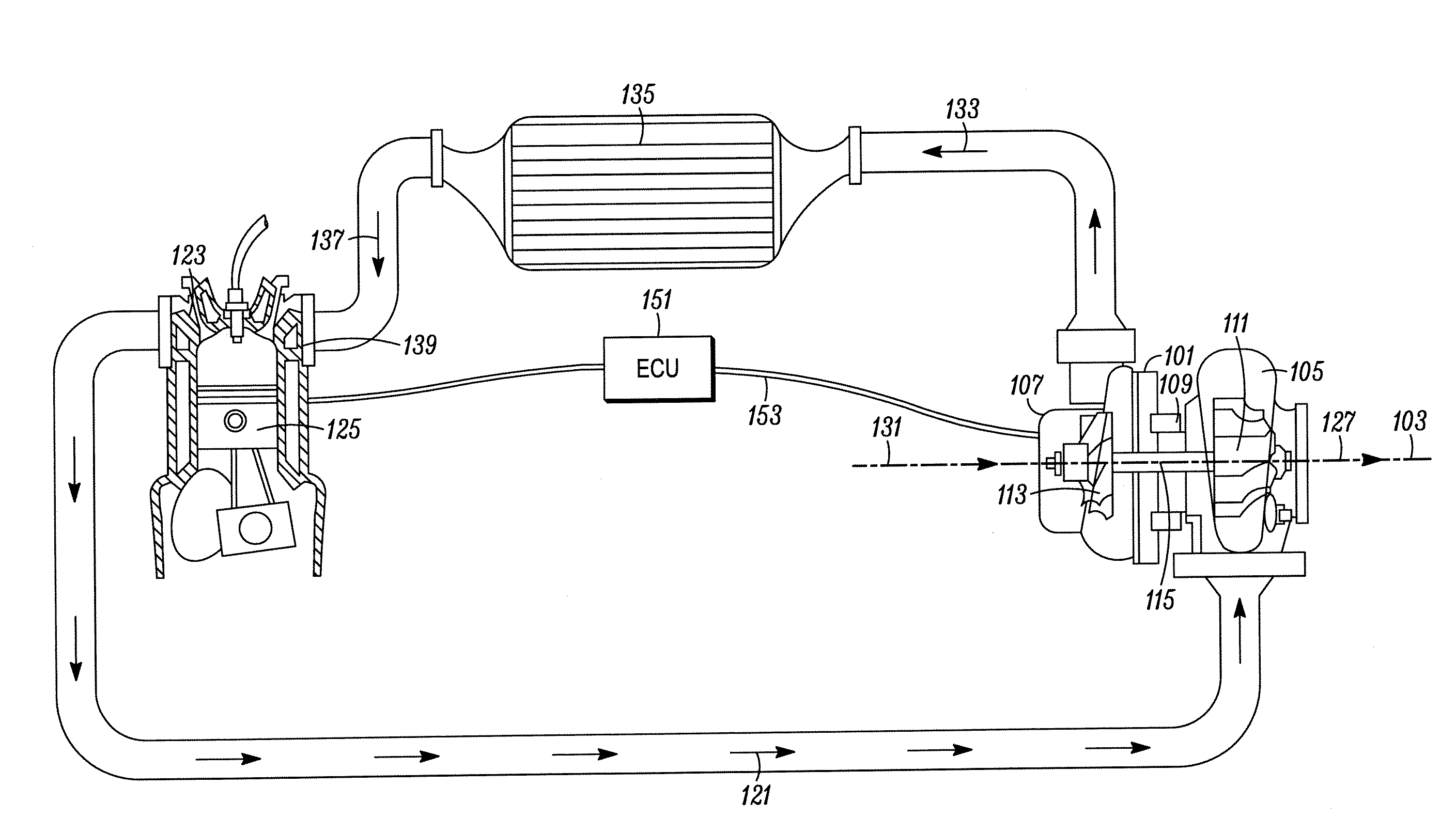
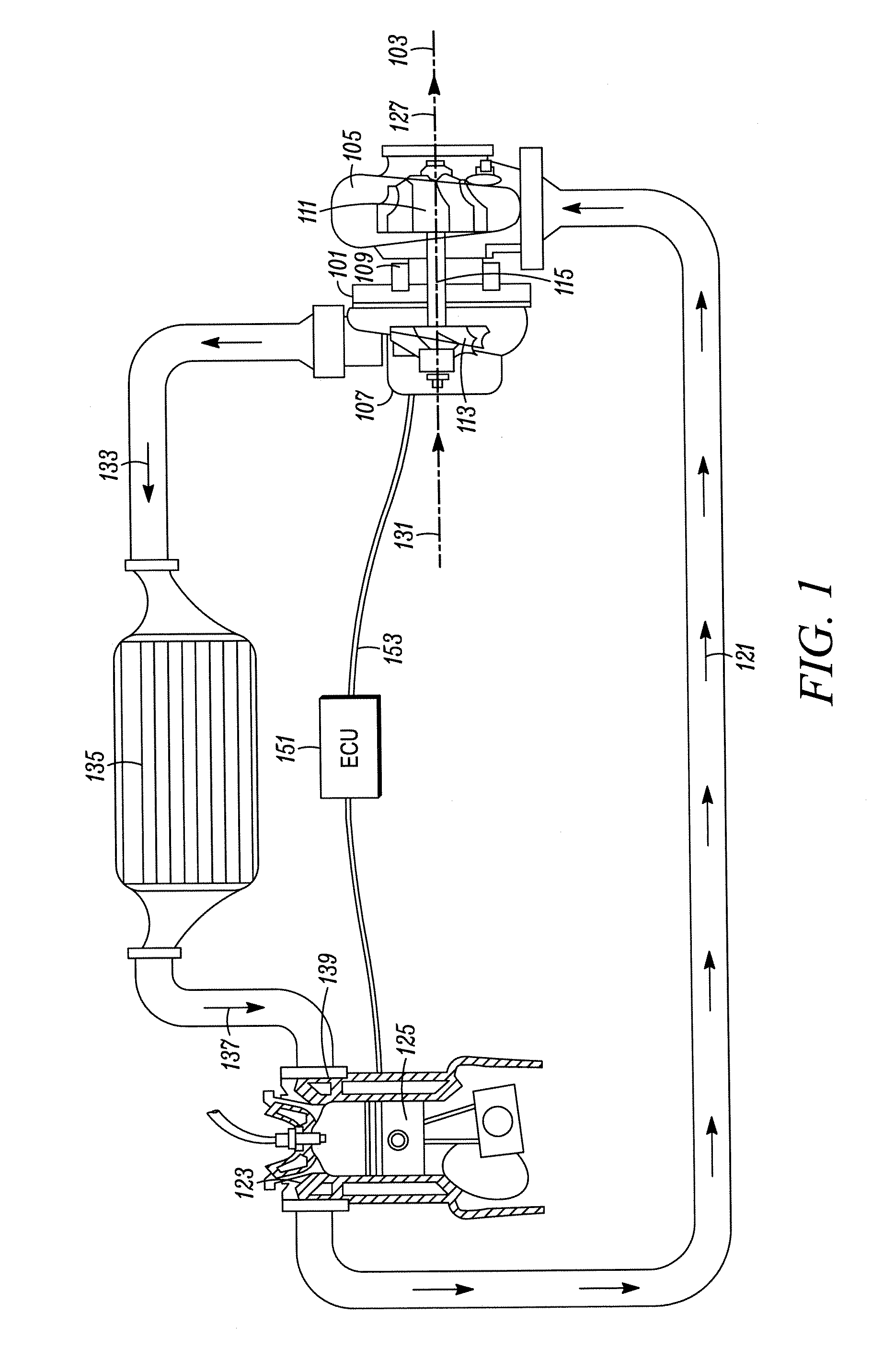
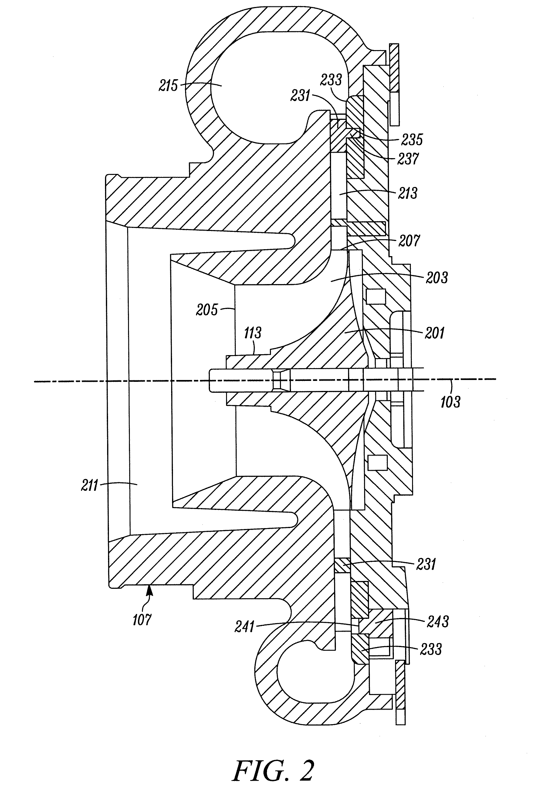
[0019]Typical embodiments of the present invention reside in a vane control system for a turbocharger, along with associated methods and apparatus (e.g., compressors, turbochargers and turbocharged internal combustion engines). Preferred embodiments of the invention are assemblies that provide for improved pressure ratios and / or related flow characteristics through the use of an actuation system configured to actuate a plurality of vanes exclusively through a plurality of discrete positions from among a ...


PUM


Abstract

A variable geometry compressor having a housing, a compressor wheel and a plurality of vanes positioned between an exducer of the compressor wheel and a housing volute. The vanes are adjustable through a range of positions, but a vane actuation system is configured to actuate the vanes through three discrete positions from among the range of positions. The actuation system has an actuator that includes an actuator housing containing a diaphragm that divides a housing chamber into two portions. Through the application of a vacuum to either chamber portion, the diaphragm drives a rod to actuate the vanes between two of the discrete vane positions, while a spring returns the vanes to the third position when no vacuum is applied. The actuator is controlled by an open-loop controller.

Description

[0001]This invention relates generally to the field of variable geometry turbochargers. More particularly, the present invention provides apparatus and methods for actuating multiple aerodynamic vanes in a diffuser of a compressor housing.BACKGROUND OF THE INVENTION[0002]In turbocharger technology a rotating compressor wheel within a compressor housing sucks air through an intake duct, compresses it in an impeller passage, and diffuses it through a diffuser into a volute. From the volute, the compressed air is supplied to an intake manifold of an internal combustion engine.[0003]The operating range of a compressor extends from a surge condition (wherein the airflow is “surging”), occurring at low airflow rates, to a choke condition (wherein the airflow is “choked”) experienced at high airflow rates. Surging airflow occurs when a compressor operates at a relatively low flow rate with respect to the compressor pressure ratio, and the resulting flow of air throughout the compressor bec...

Claims


Application Information

Patent Timeline
Patent Type & Authority Applications(United States)
IPC IPC(8): F02B71/04
CPCF01D17/165F04D29/444F04D29/462F05D2220/40F05D2270/101F05D2270/301F05D2270/66
Inventor NOELLE, PHILLIPEVAZEILLE, NICOLASMASSARD, NICOLAS
Owner HONEYWELL INT INC
Why Eureka
Try Eureka