Pneumatic Radial Tire

Inactive Publication Date: 2008-11-13
BRIDGESTONE CORP
View PDF8 Cites 21 Cited by
  • Summary
  • Abstract
  • Description
  • Claims
  • Application Information

AI Technical Summary

Benefits of technology

[0084]As described above, according to the pneumatic radial tire of the present invention, an excellent effect that good high speed

Problems solved by technology

This caused that the contact pressure between the tire and the road surface in the crown shoulder part to be extremely increased as compared to that in the crown center part, which directly led to an increase in distortion of the tire under the load.
Such a tire was actually subjected to the takeoff test (FAA TSO-C62d test) as specified by the government agency to evaluate the du

Method used


Image

  • Pneumatic Radial Tire
  • Pneumatic Radial Tire
  • Pneumatic Radial Tire

Examples


Example

[0102]A first embodiment of the pneumatic radial tire of the present invention will be described with reference to FIG. 1 to FIG. 5.

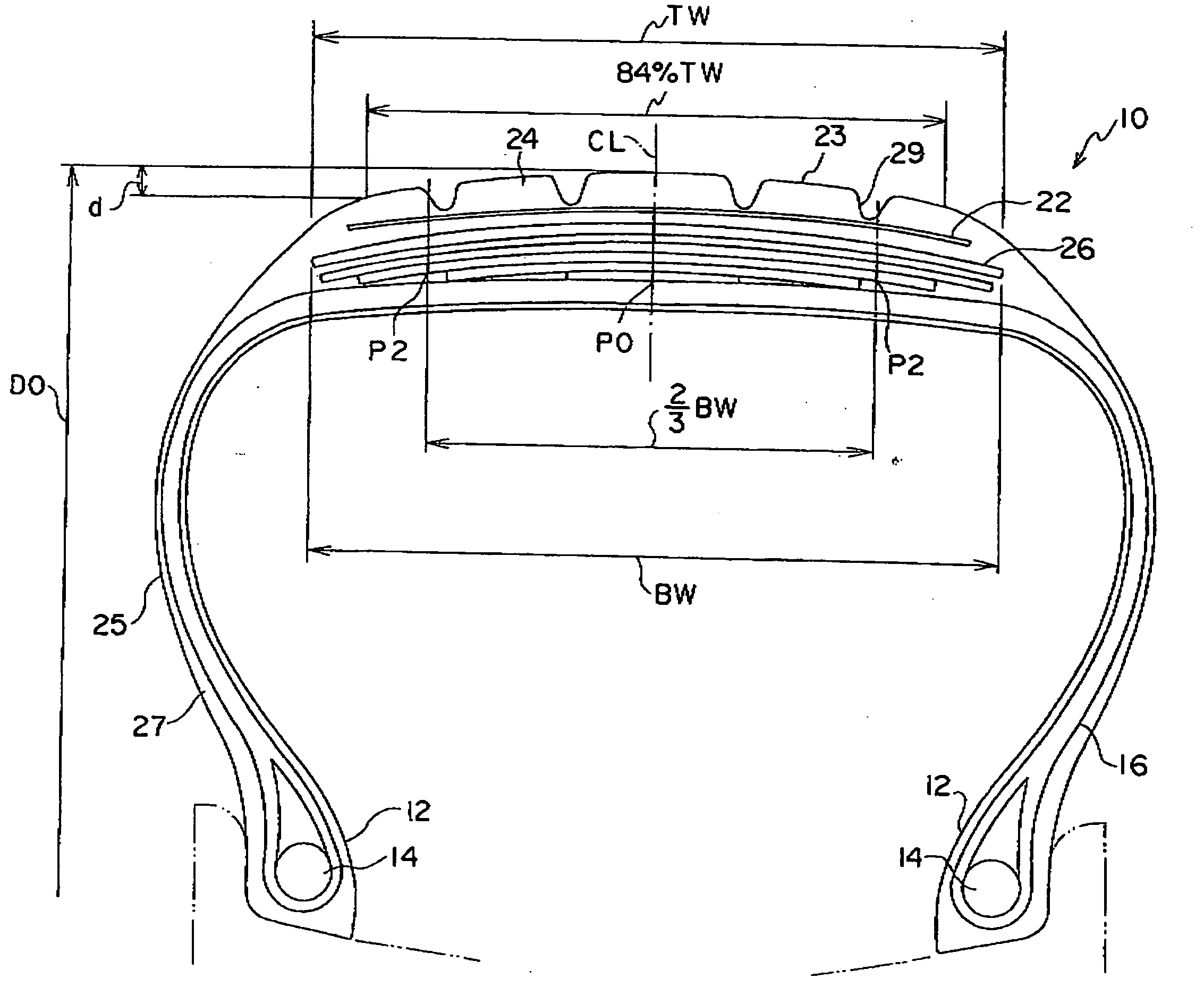
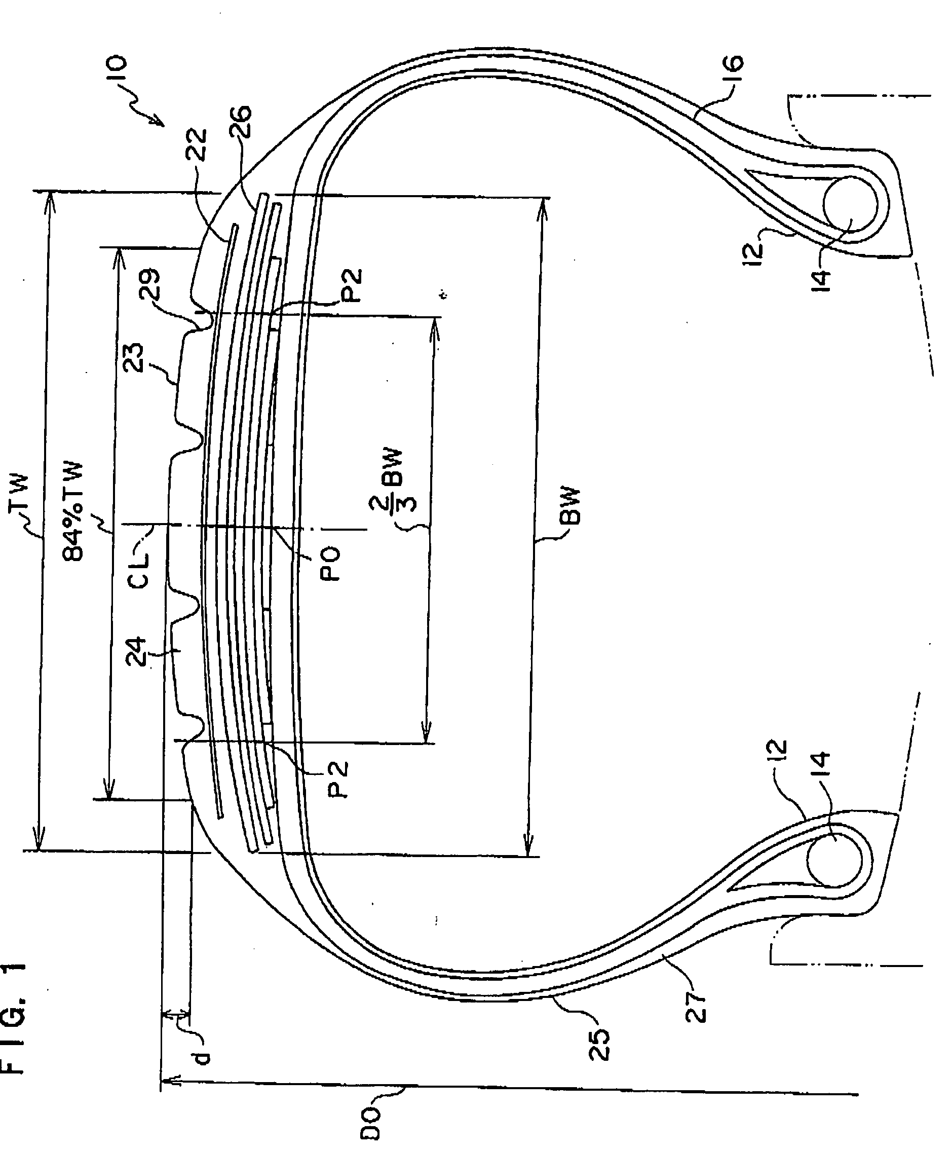
[0103]As shown in FIG. 1 and FIG. 2A, a pneumatic radial tire 10 (with a tire size of 1270×455 R2232PR) for airplane of the present embodiment comprises a bead core 14 having a round section at a bead part 12, and to this bead core 14, a carcass layer 16 made up of six carcass plies (not shown) in which rubber-coated organic fiber cords are arranged in the radial direction is anchored.

[0104]The other structural members, such as a flipper, a chafer, and the like, are the same as those in the conventional pneumatic radial tire, and illustration of them is omitted.

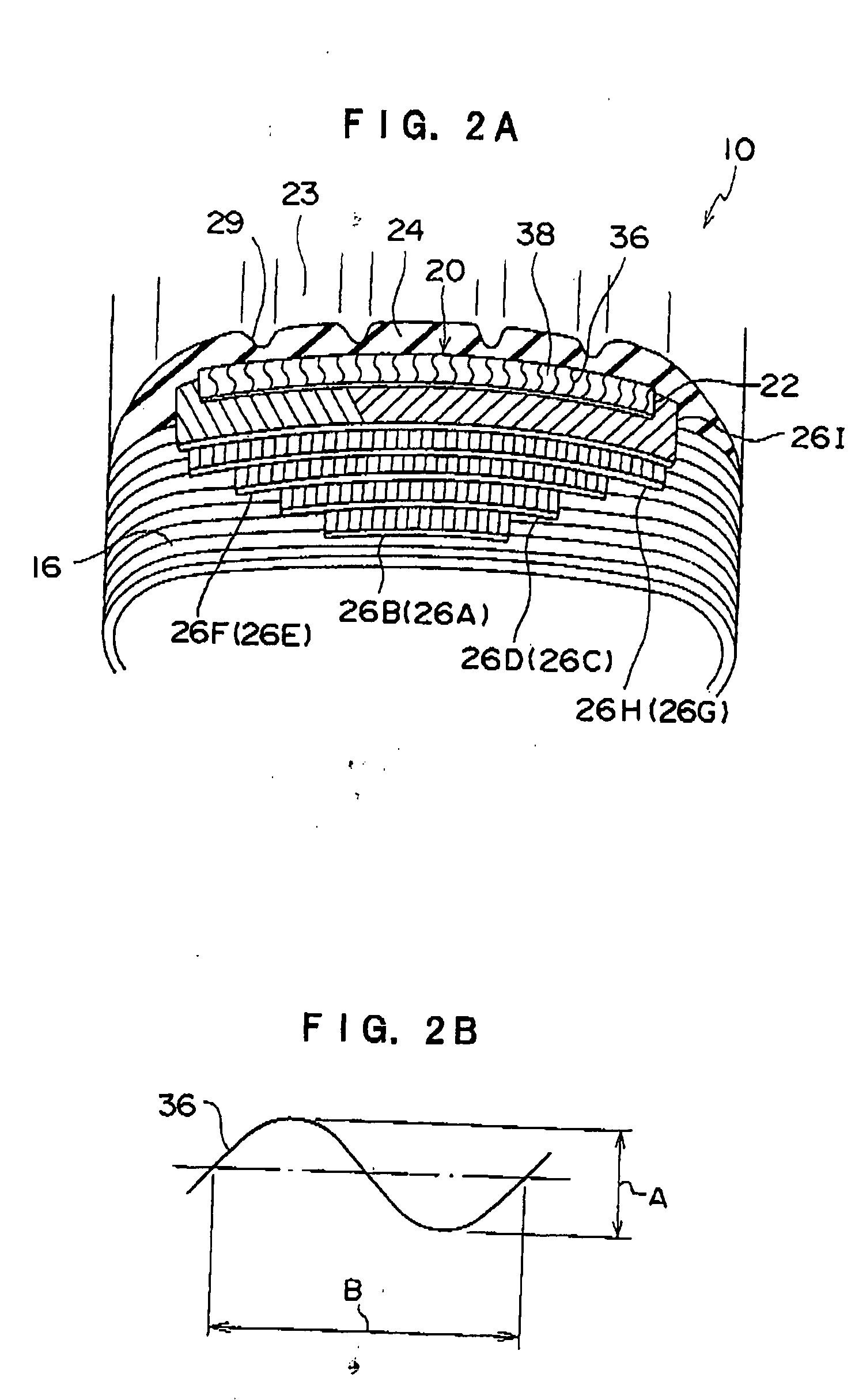
[0105]On the circumferential surface in the crown region on the outer side in the tire radial direction of the carcass layer 16, a belt layer 20; and on the outer side in the radial direction of the belt layer 20, a tread rubber layer 24 constituting a tread part 23 are provided.

[0106]In addition...

Example

Second Embodiment

[0201]Next, a pneumatic radial tire 10 pertaining to a second embodiment of the present invention will be described. The same components as those in the first embodiment are provided with the same reference numerals and signs, and the explanation thereof is omitted.

[0202]With the pneumatic radial tire 10 in the present embodiment, the material of the organic fiber cord in the first belt ply 26A to the eighth belt ply 26H in the main belt layer 26 differs from that of the pneumatic radial tire 10 in the first embodiment, and the organic fiber cord used for the first belt ply 26A to the eighth belt ply 26H in the present embodiment is a so-called hybrid cord which comprises an aromatic polyamide-based fiber and an aliphatic polyamide-based fiber.

[0203]The weight ratio between the aromatic polyamide-based fiber and the aliphatic polyamide-based fiber is preferably set from 100:10 to 100:170, and more preferably from 100:17 to 100:86.

[0204]Thereby, the tensile breaking ...


PUM

PropertyMeasurementUnit
Fractionaaaaaaaaaa
Fractionaaaaaaaaaa
Fractionaaaaaaaaaa

Abstract

A pneumatic tire for airplanes that assures a good high-speed durability and wear characteristics without its excellent durability against foreign object being impaired is provided. The number of plies of the main belt layer 26 is substantially continuously decreased from the crown center part P0 to the shoulder part, and if the circumferential rigidity in the crown center part P0 of the main belt layer 26 and the circumferential rigidity of the main belt layer 26 at the position P2 which provides ⅔ of the width of the main belt layer 26 are M0 and M2, respectively, the ratio M2/M0 between both is set at a value greater than 0.2 and smaller than 0.8, whereby, while the quantity of materials used for the main belt layer 26 being minimized, the amount of the tread rubber circumferential elongation in the tread central region at the time of air filling to a prescribed internal pressure and at the time of high speed revolution can be efficiently suppressed for suppressing the radial growth of the tire. Because the amount of circumferential elongation of the tread rubber layer 24 is suppressed, and thus the degree of tension of the tread rubber layer 24 is lowered, the resistance to penetration of a foreign object is increased, and even if a foreign object should stick into the tire, the growth of the crack can be suppressed.

Description

TECHNICAL FIELD[0001]The present invention pertains to a pneumatic radial tire, and particularly relates to a pneumatic radial tire which is suitable for airplanes, having an excellent wear resistance and thus economy, and at the same time allowing lightness to be achieved.BACKGROUND ART[0002]With conventional radial tires, and particularly pneumatic tires for airplanes, the high operating internal pressure, and the action of the centrifugal force during high speed revolution cause the tread surface to be greatly projected in the radial direction, and thus at the time of operation, the tread is brought into the state in which it is greatly elongated in the circumferential direction.[0003]In such a state, the resisting force of the tread rubber in case where the tire treads on a foreign object is weak, and the foreign object tends may penetrate into the tread rubber.[0004]With the structure of the conventional radial tire for airplanes, the belt structure uses an organic fiber having...

Claims


Application Information

Patent Timeline
IPC IPC(8): B60C11/00B60C9/00
CPCB60C9/20B60C9/2204B60C9/263B60C9/005B60C11/00B60C11/0332B60C2200/02B60C9/28D02G3/48D10B2331/02D10B2331/021
Inventor YANO, TAKESHI
Owner BRIDGESTONE CORP
Why Eureka
Try Eureka