Method for Controlling HVAC Systems

a technology of hvac system and control method, which is applied in the direction of heating types, lighting and heating apparatus, instruments, etc., can solve the problems of adjusting the fire time of the unit, not accurately determining the required temperature of the pumped water, and the measurement of the temperature of the source medium, so as to reduce the wasted heat loss of piping or ducts, reduce the inherent delay between sources and the controlled environment, and increase the circulation time

Inactive Publication Date: 2008-11-13
COCKERILL JOHN F
View PDF27 Cites 13 Cited by
  • Summary
  • Abstract
  • Description
  • Claims
  • Application Information

AI Technical Summary

Benefits of technology

[0040]It is another object of this invention to provide calculations according to a particular algorithm in order to change the source activation time in accordance with the actual changes in controlled environment demand activity over time. This aspect offers a broad application for the system to different environments. The reaction times may be adjusted to provide a smooth transition of energy supply in the same manner as can be expected by the heat loss or gains expected from the controlled environment. It removes the inherent delays between sources and the controlled environment which are caused by current methods in the field. In a heating application, higher circulation time of a generated transfer medium with a temperature of less variation from the controlled environment reduces the wasted piping or duct heat loss during periods of non circulation. Further, the use of warm rather than hot tran...

Problems solved by technology

This patent controls the fuel or fuel/air mixture, it does not adjust the fire time of the unit as a function of time.
Further this may be difficult in applications where measuring the temperature of the transfer medium is not possible or the transfer medium does not undergo a temperature change.
This requires measurement of the temperature of the source medium which can be difficult particularly where temperature measurement is not possible or the transfer medium does not undergo a temperature change.
The issue with this device is monitoring the time the pump is activated does not accurately determine the required temperature of the pumped water.
In fact this method may cause the water temperature to be increased unnecessarily, particularly, where for heating comfort it is desirable to maintain longer circulation time with lower temperature to maintain more even temperature distribution and to replace only the heat loss of the controlled environment.
The method does not particularly control the activation time of a heating or cooling unit.
The principal issue with the prior art is that all require extraneous temperature measurements, such as the temperature outside the controlled environment or the temperature of the transfer medium.
Another disadvantage of some prior art is it seeks to gain efficiency in prolonged off time of the heating or cooling source and therefore reducing the number of starts for the heating or cooling unit.
This is not necessarily efficient as each time the circulation pump stops, high temperature transfer medium looses energy to the walls of the pipes or duct in which it is housed.
For many systems where the heating or cooling unit is located a considerable distance from the controlled environment, the energy is lost to...

Method used


Image

  • Method for Controlling HVAC Systems
  • Method for Controlling HVAC Systems
  • Method for Controlling HVAC Systems

Examples


Embodiment Construction

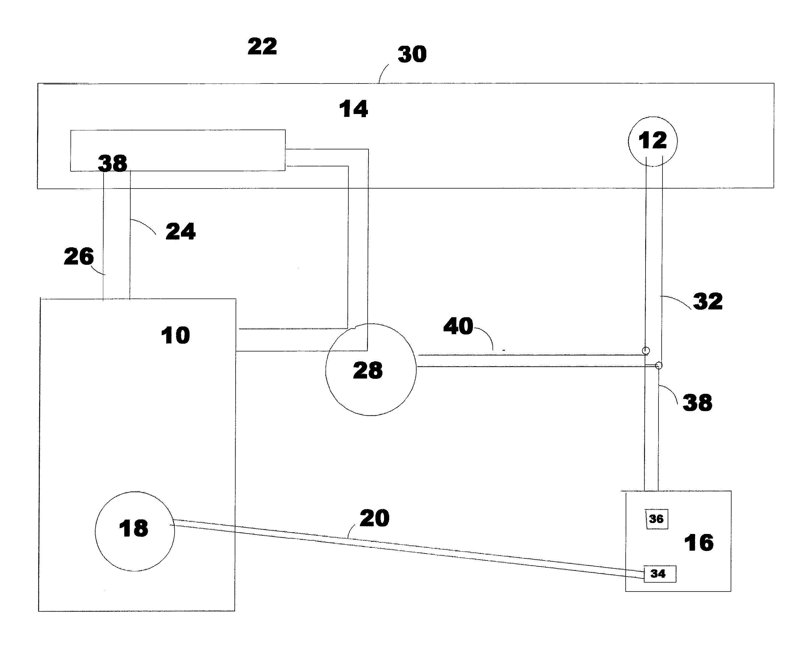
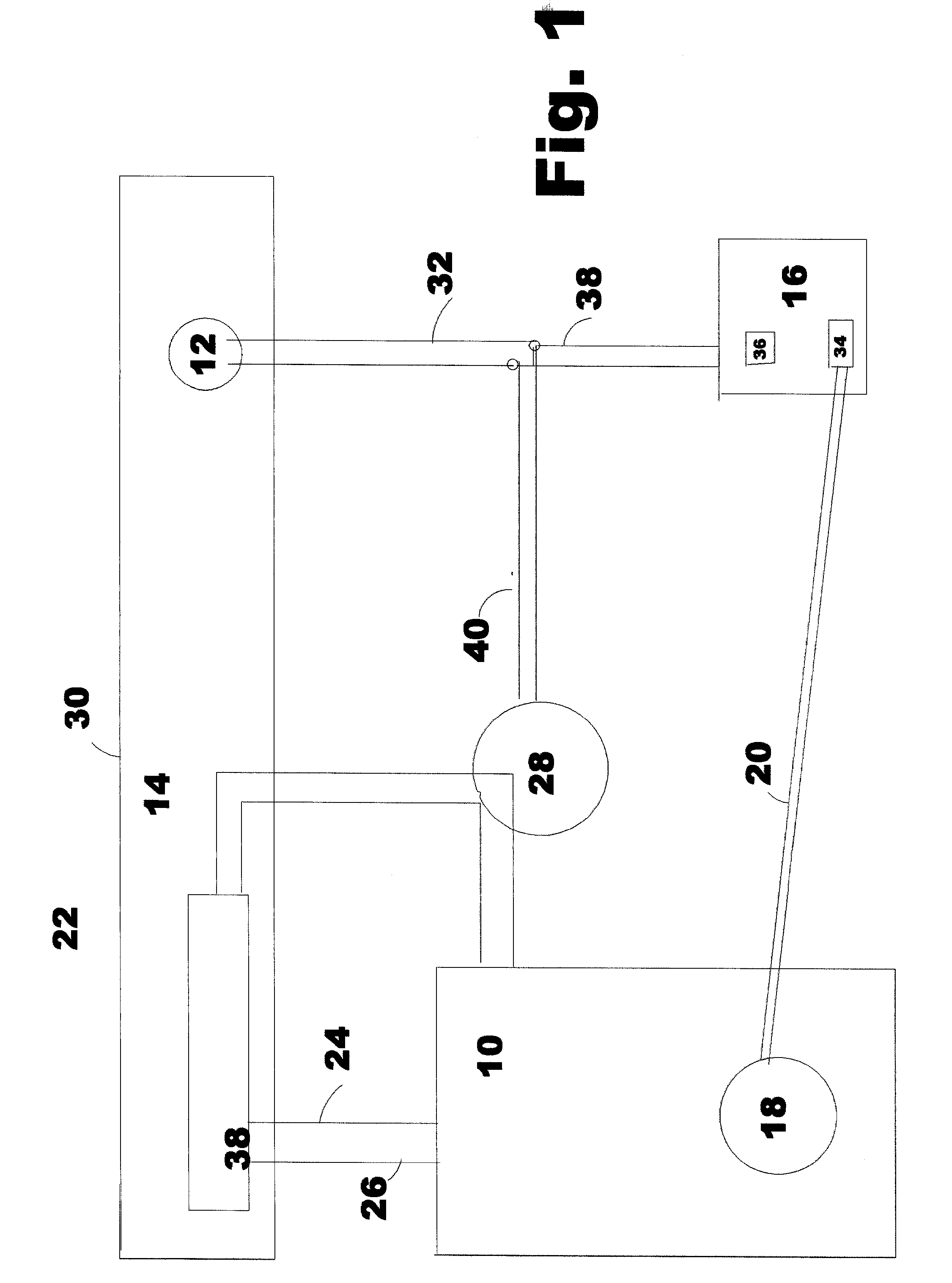
[0046]As shown in FIG. 1, a heating, cooling or ventilation system 10 is used to satisfy the heating, cooling or ventilation needs of a controlled environment 14, such as a house or office building or just a single room. A liquid or gas transfer medium 24, such as air, steam, gas or fluid, may be utilized. As a preferred embodiment, reference will be made to a system for controlling the temperature in a controlled environment. However, the control system of the present invention may be utilized for efficient control of a variety of equipment utilizing a circulating transfer medium to effect a change in a controlled environment. Such other systems may include air filtration, humidification or dehumidification systems.

[0047]The actual temperature in the controlled environment 14 is determined by the BTU exchanged (heat lost or gained) with the exterior environment 22 and the BTUs added or removed by a heating or cooling system 10. The exterior environment 22 may be any space outside t...


PUM


Abstract

The herein method for adjusting the source activation time of a heating or cooling source is based upon variation in temperature sensor or thermostatic means activity within a controlled environment, and involves activating and deactivating the heating or cooling source to provide precise heating or cooling BTU replacement. This method changes the priority of heating and cooling management from a fixed source output, which is called upon by a controlled environment thermostat, to a system of adjusting the source output to the precise delivery of source output to the needs of the enclosed environment at an ideal thermostat demand ratio within the controlled environment.

Description

BACKGROUND OF THE INVENTION[0001]1. Field of the Invention[0002]The invention relates to the commercial and residential construction and maintenance industries and, in particular, to devices for optimally controlling the activation of boilers, furnaces, ventilation units, humidifiers, fresh air handlers and air conditioning means.[0003]2. Summary of the Prior Art[0004]It is well known, all buildings, of what ever type, shape and size, whether commercial or residential, require some type of heating, ventilation and cooling. Depending on the particular building, there may be one or more boilers, furnaces, air conditioners, heat pumps, heat exchangers, ventilation units, humidifiers, dehumidifiers, solar units or similar means, hereinafter “sources”. Each is controlled by at least one sensor which may include programmable thermostats, controllers, control mechanisms, computers, control modules or the industry equivalents. Based on the temperature setting and the room temperature, the t...

Claims


Application Information

Patent Timeline
IPC IPC(8): F23N5/20G05D23/30
CPCF23N5/203F24F11/006F24F2011/0064G05D23/1951F24F11/30F24F11/62F24F11/65
Inventor COCKERILL, JOHN F.
Owner COCKERILL JOHN F
Why Eureka
Try Eureka