
Inductor

a technology of inductor and inductance, which is applied in the direction of transformer/inductance details, inductances with magnetic cores, inductances, etc., can solve the problems that affect the efficiency of embedded inductor, and achieve good insulating and magnetic properties, maintain the overall magnetic property, and improve the effect of magnetic permeability

Inactive Publication Date: 2008-11-13
DELTA ELECTRONICS INC
View PDF15 Cites 14 Cited by
  • Summary
  • Abstract
  • Description
  • Claims
  • Application Information

AI Technical Summary

Benefits of technology

[0012]As mentioned above, the inductor of the invention uses at least one insulated magnetic material with good insulating and magnetic properties, the mixture of the insulated magnetic material and a magnetic material, or the insulated magnetic material enveloping the magnetic material, so that the magnetic materials inside the magnetic body are insulated from each other. In comparison with the related art, the insulated magnetic material of the invention is magnetic. Therefore, it simultaneously achieves the goals of insulation as well as maintaining the overall magnetic property. The inductor of the invention thus has better magnetic permeability and saturation magnetic flux density, thereby contributing to high inductance.

Problems solved by technology

Either case mentioned above definitely affects the efficiency of the embedded inductor.

Method used


Image

  • Inductor
  • Inductor

Examples


Embodiment Construction

[0015]The present invention will be apparent from the following detailed description, which proceeds with reference to the accompanying drawings, wherein the same references relate to the same elements.

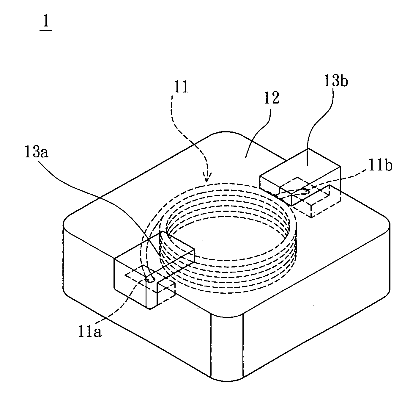
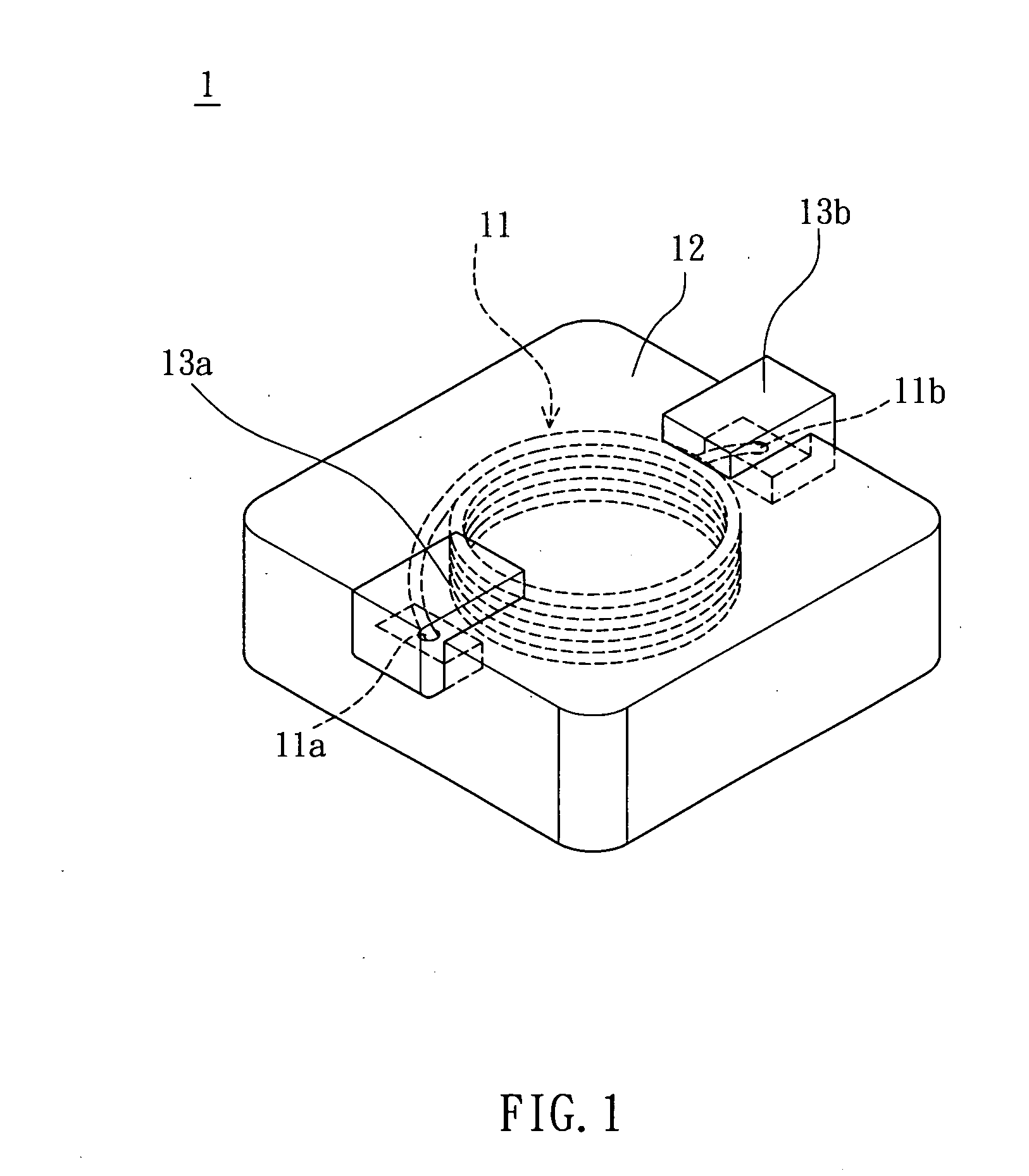
[0016]FIG. 1 is a schematic view of an inductor 1 according to an embodiment of the invention. The inductor 1 includes a coil 11 and a magnetic body 12. In this embodiment, the inductor 1 is, for example but not limited to, an embedded inductor.

[0017]The magnetic body 12 is used to cover the coil 11. In practice, the coil 11 can be made by winding a round, square or flat wire. The coil 11 has a first end 11a and a second end 11b, which can be directly used as the pins for the inductor 1 to connect with external devices. Alternatively, the first end 11a and second end 11b can also be connected with pins 13a and 13b, which are then connected with external devices.

[0018]The magnetic body 12 is made by mixing at least one insulated magnetic material and at least one resin. Explicitly spea...


PUM

PropertyMeasurementUnit
temperatureaaaaaaaaaa

Abstract

An inductor includes a coil and a magnetic body. The magnetic body covers the coil. The magnetic body includes at least one magnetic material, at least one insulated magnetic material and at least one resin. The magnetic material is enveloped by the insulated magnetic material. Alternatively, the magnetic body is made by mixing the insulated magnetic material with the magnetic material.

Description

CROSS REFERENCE TO RELATED APPLICATIONS[0001]This Non-provisional application claims priority under 35 U.S.C. §119(a) on Patent Application No. 096116766 filed in Taiwan, Republic of China on May 11, 2007, the entire contents of which are hereby incorporated by reference.BACKGROUND OF THE INVENTION[0002]1. Field of Invention[0003]The invention relates to an inductor and, in particular, to an embedded inductor.[0004]2. Related Art[0005]The miniaturization trend of electronic products demands that basic and important components such as the inductors have to be reduced in both weight and size. Moreover, how to maintain low loss and high efficiency while reducing the device sizes is a more important goal of the industry.[0006]To provide an inductor that can stand a large electrical current, operate at high frequencies, has low core loss, and reach no air gap and high operating efficiency, the embedded inductor has been introduced. A conventional embedded inductor includes a coil and a m...

Claims


Application Information

Patent Timeline
Patent Type & Authority Applications(United States)
IPC IPC(8): H01F27/02
CPCH01F17/04H01F2017/048
Inventor LEE, CHENG-HONGHSUEH, YU-LINHUANG, YI-HONG
Owner DELTA ELECTRONICS INC
Learn More