[0011]The invention provides a scene graph, which represents data and a set of processes thus providing an enhanced approach to the scene graph concept. With this approach the scene graph becomes a rendering description of the data rather than a world description. Previously known scene graphs represent a structure of objects and their attributes. This approach can be found, for instance, in environments based on
Java3D or
VRML. An
advantage of the invention can be explained in the term of transparency. In the
Java3D approach transparency is a surface attribute where, as in the embodiment of the invention, transparency is a rendering
algorithm based on the rendering order, which is
user defined, and optionally applied on a blending process. This fundamental difference removes the previous limitations and allows the user to express new algorithms directly in the scene graph, in terms of processes and rendering order. The scene graph has a notation of the traversing order, which together with the types of nodes, the nodes position, the nodes functionality and nodes state determine the rendering order. Thus the user can express any effects supported by the underlying rendering pipeline directly in the scene graph.
[0012]A further object is to provide an API for the scene graph that is easy to use, still giving control of the actual rendering order and optimization to the user. The scene graph is extensible allowing the user to experiment and express new
rendering algorithms in the scene graph
semantics. The
semantics of the scene graph allows the user to express optimizations. The scene graph is particularly suitable for a CPU / GPU environment, or similar. The API and the scene graph
semantics enable the user to optimize rendering in computerized systems with both single and multiple CPU.
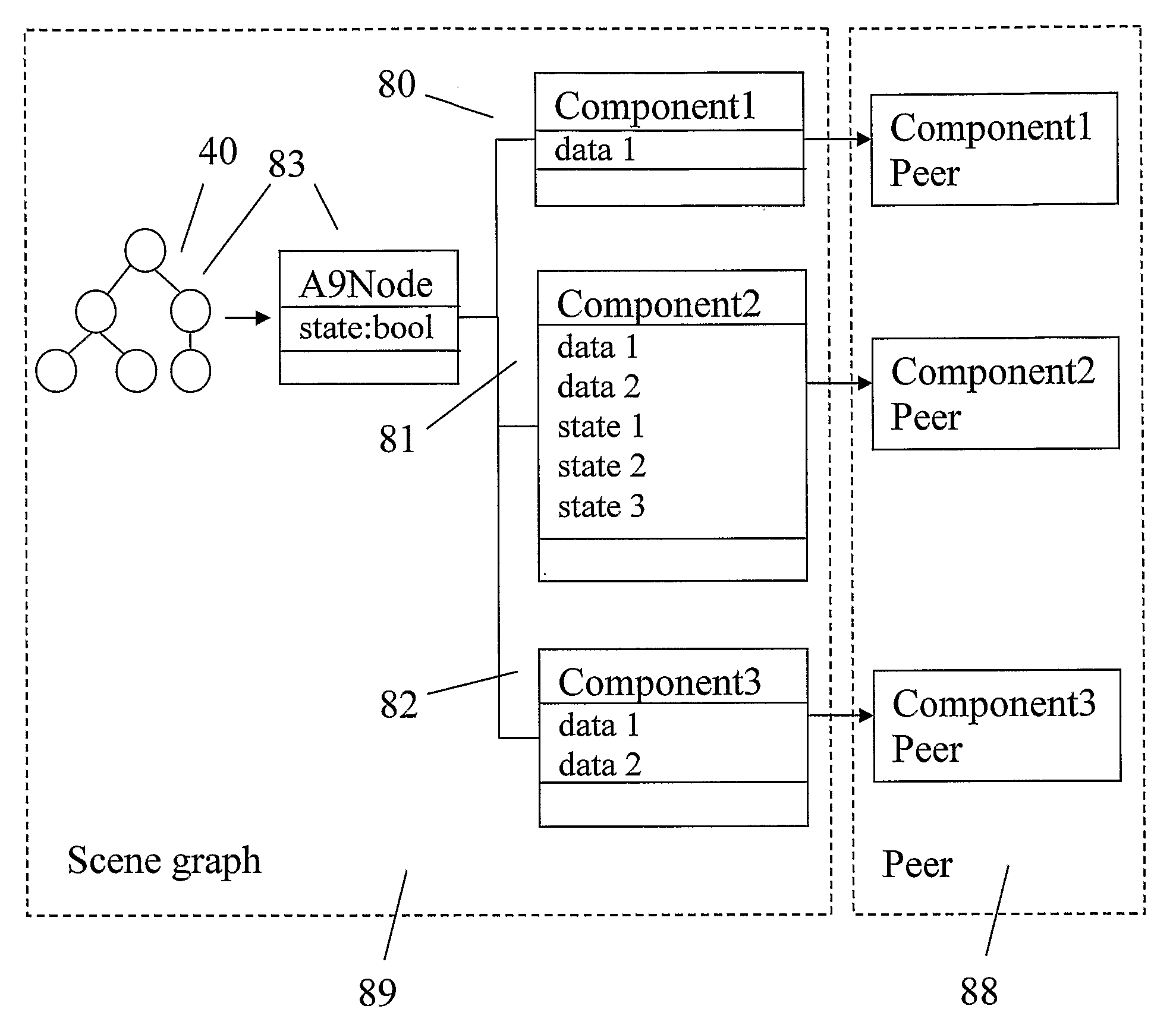
[0013]The invention enables the user to add an additional node to the scene graph, where the order in which scene graph data is sent down the rendering pipeline, depends on the position of the added node in the scene graph and its state. An added node may have a number of children. The added node and its children may comprise a rendering
algorithm for 3D graphical presentation. In contrast to other scene graphs the rendering algorithm is previously unknown to the
system software traversing the tree. In other previously known scene graphs such algorithms for 3D graphical presentations are not possible for a user to access, unless the
system software is updated with a version supporting the algorithm. Functions of the new algorithm may have its origins from the vendor of the graphical board comprising the GPU. It may, for instance, be a new algorithm for handling reflections in surfaces such as glossy furs.
[0014]Yet another feature of the scene graph is the ability for the user to extend a node so that certain state of the node is used to determine if children of the node are to be traversed. Such an extended node enables the user to optimize the algorithm.
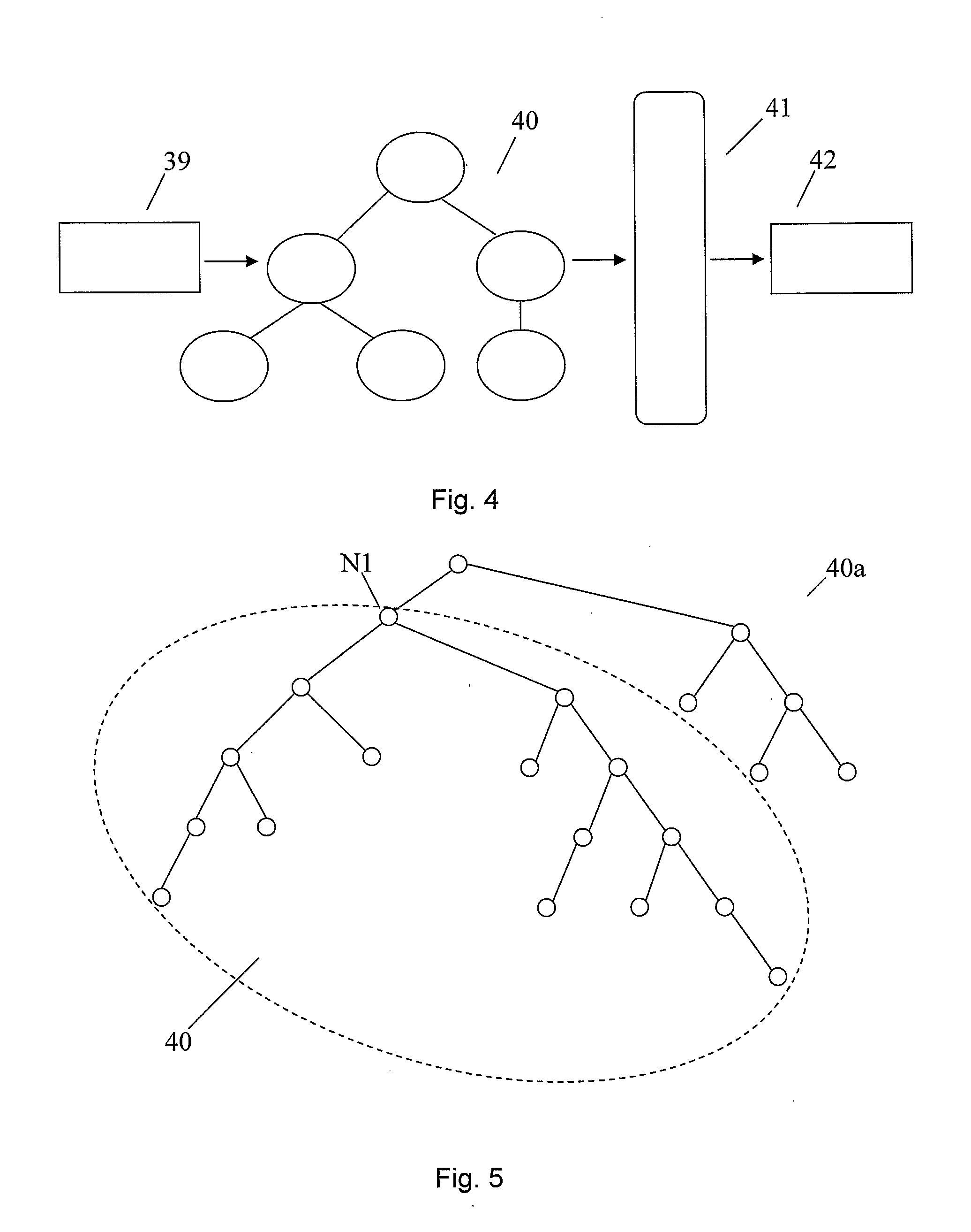
[0015]The scene graph is constructed by assembling a set of nodes thus creating a
directed acyclic graph. In contrast to previously known scene graphs, any node may be set as a starting point node for scene
graph traversal. The node may be a
base class the scene graph is built from and defines the traversing order of its children. A node typically keeps a
list of its children and any node can be added as a child to another node. The scene graph is traversed from top to bottom, left to right (or
right to left). All scene graph nodes guarantee this traversal order. A user can extend any node and add restrictions related to in how the
user defined order should be traversed. In one embodiment the restriction relates to if a condition, regarding the state of a node is fulfilled at the time of a rendering pass. This gives the user total control over the traversal order and the rendering process. This also enables the user to build render order dependent optimizations, directly into the graph, this in contrast to earlier known scene graphs and their related APIs. A rendering API, according to the invention, is separated from the underlying hardware API, such as Direct3D or
OpenGL.
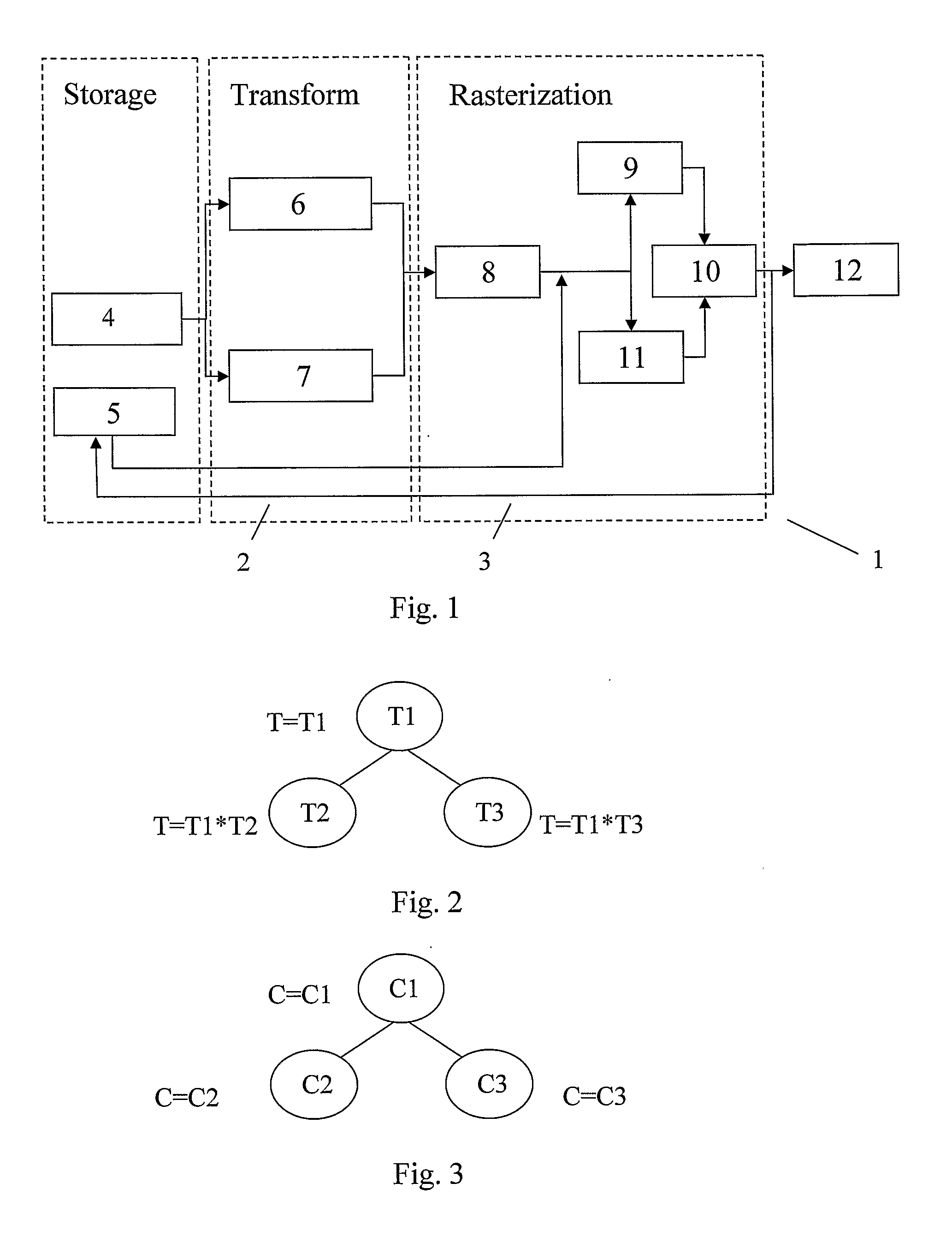
[0016]Traversal of the scene graph is repeated number of times per second. The node where to start traversal of the scene graph may be changed by the user from one traversing pass to the next. Traversal of the scene graph is defined in two passes; the update and the render pass. This design is preferable in order to be able to optimize the use of
hardware structure, such as to maximize the Asymmetrical Multi Process (ASMP) behaviour of the CPU / GPU architecture. The update pass may be time dependent and utilize only CPU resources. The intended use is to update states of nodes and perform CPU heavy calculations such as
animation and geometry deformations in the update pass. The update pass can be run as single or multithreaded, both on traversal and node levels without need of synchronization. The render pass communicates with the GPU and uses as little CPU resources as possible. The two passes allow the user to optimize the system for the best possible ASMP behaviours. The architecture allows multithreaded CPU behaviour on each node in the render pass but not on the actual traversal. With a single threaded traversal, data can be sent down the rendering pipeline as fast as possible without any synchronization. Multithreaded traversal, when rendering, makes less sense since all rendering in the end is more or less order dependent. When the data has been sent down the pipeline the GPU can start
processing data independently from CPU. As the GPU is
processing geometry the CPU resources can be assigned to the update pass. The separation of update and render also allows partitioning resources between frames, where only parts of a frame need to be updated in each frame.

