Electric Disabling Device with Controlled Immobilizing Pulse Widths

a technology of immobilizing pulse width and electric disabling device, which is applied in the direction of ammunition projectiles, transportation and packaging, weapons, etc., can solve the problems of delivering an incapacitating electric shock, unable to be incapacitated, and shock may be lethal, so as to achieve optimal immobilizing duty cycle, reduce total energy, and incapacitate nerve tissue.

Inactive Publication Date: 2008-11-13
STINGER SYST
View PDF14 Cites 13 Cited by
  • Summary
  • Abstract
  • Description
  • Claims
  • Application Information

AI Technical Summary

Benefits of technology

[0008]It is an object of the invention to tailor the energy delivery sequence of a stun device, such as a stun gun, to more thoroughly incapacitate nerve tissue while delivering less total energy than is the case with prior art stun devices. In preferred embodiments this is provided by applying incapacitating pulses lasting between 150 and 300 microseconds. Further, because nerve tissue has a recovery period (depolarization and refractory period) of approximately 4 milliseconds, preferred embodiments of the invention deliver a plurality of energy pulse groups having an interval of about 4 milliseconds between pulse groups.
[0009]A preferred embodiment of the invention provides an electric disabling device configured as a handgun for immobilizing a human or animal target. This gun, similar to other such devices, comprises at least two projectile electrodes for positioning at spaced apart contact points adjacent a target and a suitable propelling means, such as pressurized gas or a pyrotechnic charge, for propelling the projectile electrodes from the device towards the target. The preferred device also comprises a transformer having primary and secondary windings, a capacitor, and a DC power supply operable to charge the capacitor element. Each end of the secondary winding of the transformer is electrically connected to only one of the two electrodes The preferred embodiment also comprises a semiconductor switching device controllable by a control circuit to repeatedly switch between a conducting and a non-conducting state so as to cause pulses of current to flow from the capacitor through the primary winding of the transformer. In particular preferred embodiments, the semiconductor switching element is an insulated gate bipolar transistor (IGBT).
[0010]In an initial preferred contact-establishing method of operating such an electric disabling device the capacitor is initially charged from the DC power supply to a predetermined maximum voltage and the semiconductor switching device is controlled by the controller to close for a discharge interval having a selected duration of more than 15 but less than 50 microseconds. This assumes that a step up transformer with a primary inductance of about 50 micro-henries is utilized. At the end of the selected discharge interval the switching element is opened and held open for a pause interval having a selected duration at least as long as the discharge interval and at most five times as long as the discharge interval. The discharge and pause steps are then repeated at least once and preferably between five and ten times until the capacitor is substantially fully discharged.
[0011]In a second preferred immobilizing method of operating such an electric disabling device, the capacitor is charged from the DC power supply and the semiconductor switching device is controlled by the controller to close for a discharge interval having a duration of more than 5 but less than 20 microseconds. At the end of the discharge interval the switching element is opened and held open for a pause interval having a selected duration at least as long as the discharge interval and at most five times as long as the discharge interval. The number of such switching actions is adjusted to discharge the capacitor to approximately 40% of its maximum rated energy storage value and span a duration of approximately 200 microseconds. Then, during an idle period of substantially 4 millisec the capacitor is partially recharged to 50% or more of its rated capacity and then the above process is repeated until the capacitor is substantially fully discharged. Thereafter, the capacitor is fully recharged and the process is repeated after a recharge delay between 50 and 100 milliseconds.
[0012]A particular preferred method of operating a disabling device of the invention comprises carrying out the first and second methods in sequence. That is, the controller controls the switching element to initially deliver high voltage pulses optimized to both fire the pyrotechnic charge and establish contact and to then deliver immobilizing pulses. If the projectile electrodes are not initially in intimate contact with the target, as is usually the case, the secondary of the transformer is essentially open-circuited so that pulsing the primary causes ‘flyback’ voltages in the secondary that can reach fifty to seventy kilovolts, which is known to be high enough to ionize the air between each projectile electrode and the target and to lead to intimate electrical contact. Once contact has been established to the target, the secondary of the transformer is no longer open-circuited and pulsing the primary results in lower voltage, higher current pulses in the secondary that can be controlled to have an optimal immobilizing duty cycle. In particular preferred embodiments, a 100 V DC power supply charges the capacitor, which is discharged through a 55:1 step-up transformer that outputs about a 2 kV pulse to the target, which is generally viewed as about a 1 kΩ load once contact has been established.

Problems solved by technology

Generally speaking, there are two limiting concerns in delivering an incapacitating electric shock.
At one extreme, if too little energy is delivered to a targeted individual, he or she may not be incapacitated and may be able to persist in an attack on a police office.
On the other hand, if extremely large electrical currents are delivered, the shock may be lethal, rather than merely incapacitating.

Method used


Image

  • Electric Disabling Device with Controlled Immobilizing Pulse Widths
  • Electric Disabling Device with Controlled Immobilizing Pulse Widths
  • Electric Disabling Device with Controlled Immobilizing Pulse Widths

Examples


Embodiment Construction

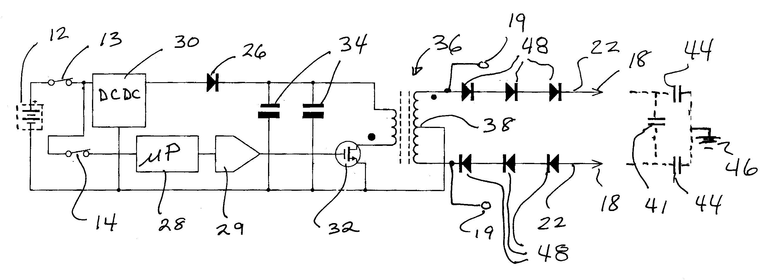
[0022]In studying this Detailed Description, the reader may be aided by noting definitions of certain words and phrases used throughout this patent document. Wherever those definitions are provided, those of ordinary skill in the art should understand that in many, if not most instances, such definitions apply to both preceding and following uses of such defined words and phrases. At the outset of this Description, one may note that the terms “include” and “comprise,” as well as derivatives thereof, mean inclusion without limitation; the term “or,” is inclusive, meaning and / or. Moreover, inasmuch as the preferred embodiment described herein involves controlled capacitive storage of electrical charge and subsequent discharge of it, it should be noted that the term ‘capacitor’ is sometimes used herein to denote either or both of a single physical component and various combinations of such components that can be viewed as being equivalent to a single capacitive component. In particular...


PUM


Abstract

A capacitive discharge stun-gun uses a flyback output circuit in which a semiconductor switch operates under control of a controller or suitable logic circuitry. The flyback circuit can deliver 50-65 kV pulses to a pair of electrodes in order to ionize air adjacent a target in order to initiate good electrical contact. When the electrodes are in good contact with the target, the flyback circuit delivers current at a lower voltage. In one mode of operation the stun-gun is controlled to initially deliver wider pulses optimized for causing air breakdown and to then deliver a series of shorter pulses in pulse groups optimized for causing involuntary muscle cramping.

Description

BACKGROUND OF THE INVENTION[0001]1. Field of the Invention[0002]The invention generally relates to electric systems and devices that generate and accumulate charge for application to living beings. More specifically, the invention relates to electric disabling devices commonly referred to as stun-guns, stun-batons or the like for delivering an incapacitating, but less than lethal, sequence of electric shocks to a person.[0003]2. Background Information[0004]Hand-held stun-guns are widely used by police officers to subdue uncooperative or potentially dangerous individuals by subjecting them to electric current pulses inducing incapacitating muscle cramps. The jolt from a stun gun is intended to cause such severe cramping as to prohibit locomotion and to cause the victim to fall to the ground. Generally speaking, there are two limiting concerns in delivering an incapacitating electric shock. At one extreme, if too little energy is delivered to a targeted individual, he or she may not b...

Claims


Application Information

Patent Timeline
Patent Type & Authority Applications(United States)
IPC IPC(8): F41B15/04
CPCF41H13/0025H05C1/06
Inventor SALIGA, THOMAS V.
Owner STINGER SYST
Why Eureka
Try Eureka