
Automatic zero voltage switching mode controller

a zero-voltage switching and controller technology, applied in the direction of dc-ac conversion without reversal, process and machine control, instruments, etc., can solve the problems of power supply switching transients not being fully removed from the output signal, waste of another watt as heat, and inefficient efficiency, so as to minimize heat generated by the output switching stage and maximize efficiency , the effect of negligible heat sinking

Active Publication Date: 2008-11-13
HARMAN INT IND INC
View PDF25 Cites 35 Cited by
  • Summary
  • Abstract
  • Description
  • Claims
  • Application Information

AI Technical Summary

Benefits of technology

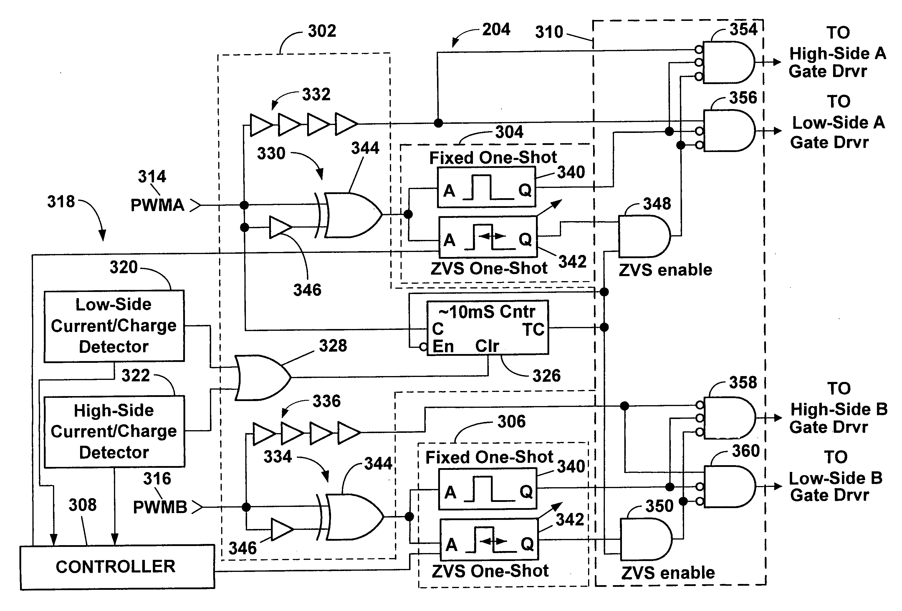
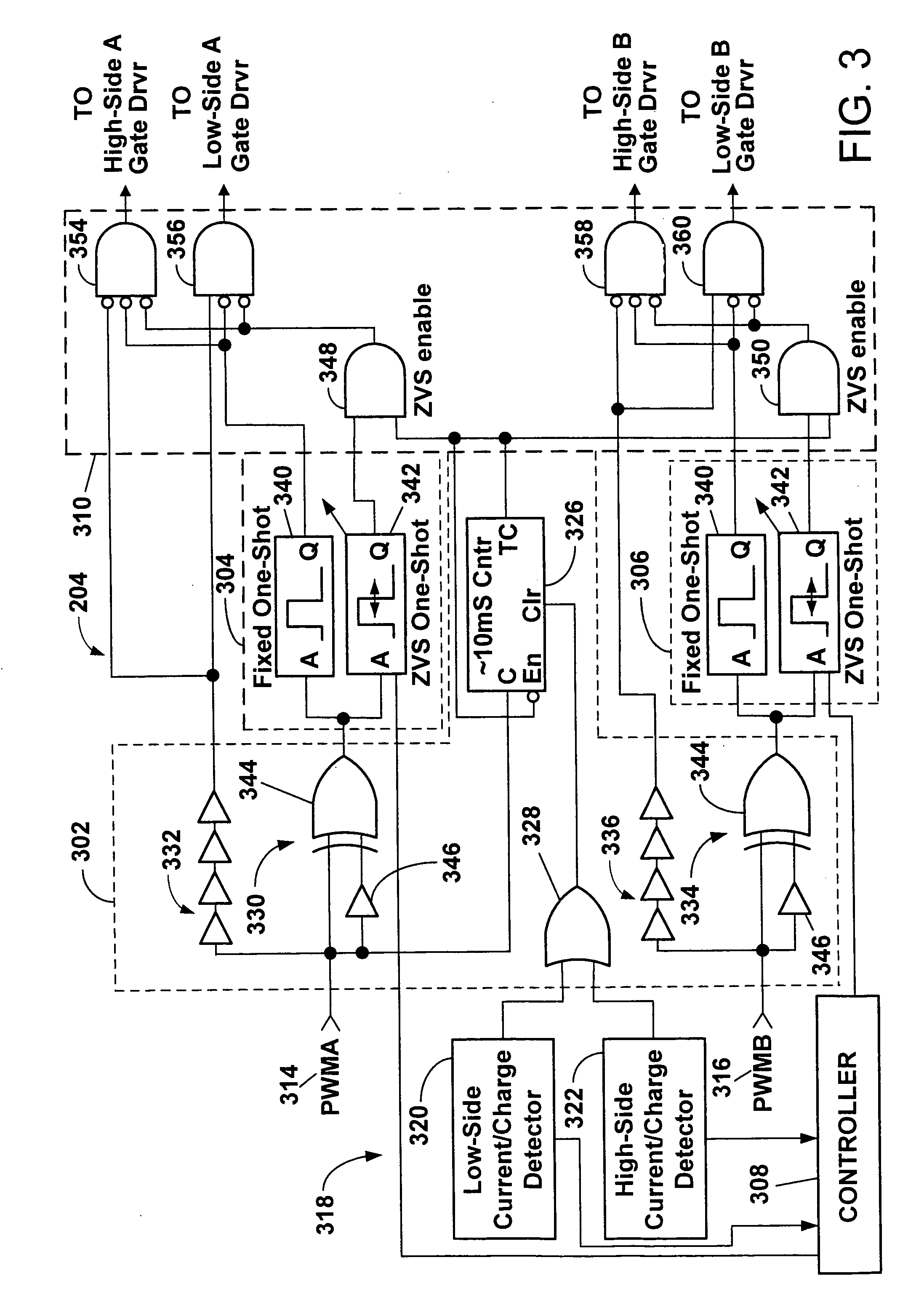
[0013]As a result of the automatic control of the ZVS dead-time, efficiency is maximized during quiescent conditions. Thus, in a large amplifier, such as an amplifier with a two channel switching stage formed on an IC capable of operation at up to 125 or 150 watts per channel, heat generated by the output switching stage is minimized during quiescent conditions. As such, the individual output stage switches may be placed on an integrated circuit (IC) in relatively close proximity with relatively small, or negligible heat sinking. In addition, since the ZVS dead-time is disabled or minimized at operating conditions in which load currents are outside a predetermined range, linearity of operation of the amplifier is optimized.

Problems solved by technology

Consequently, they are typically inefficient.
In general, for every watt of power output capability by a Class A amplifier, another watt is wasted as heat.
The downside of these designs is complexity and the risk that power supply switching transients will not be fully removed from the output signal.
In addition to greater relative efficiency, relatively lower heat losses may result in use of relatively smaller heat sinks.
An amount of time is required by the switch devices to turn off and on.
If both switch devices are closed at the same time, potentially destructive shoot-through current that travels directly from supply rail to rail may result.
Too much dead-time may result in distortion in the output signal.

Method used


Image

  • Automatic zero voltage switching mode controller
  • Automatic zero voltage switching mode controller
  • Automatic zero voltage switching mode controller

Examples


Embodiment Construction

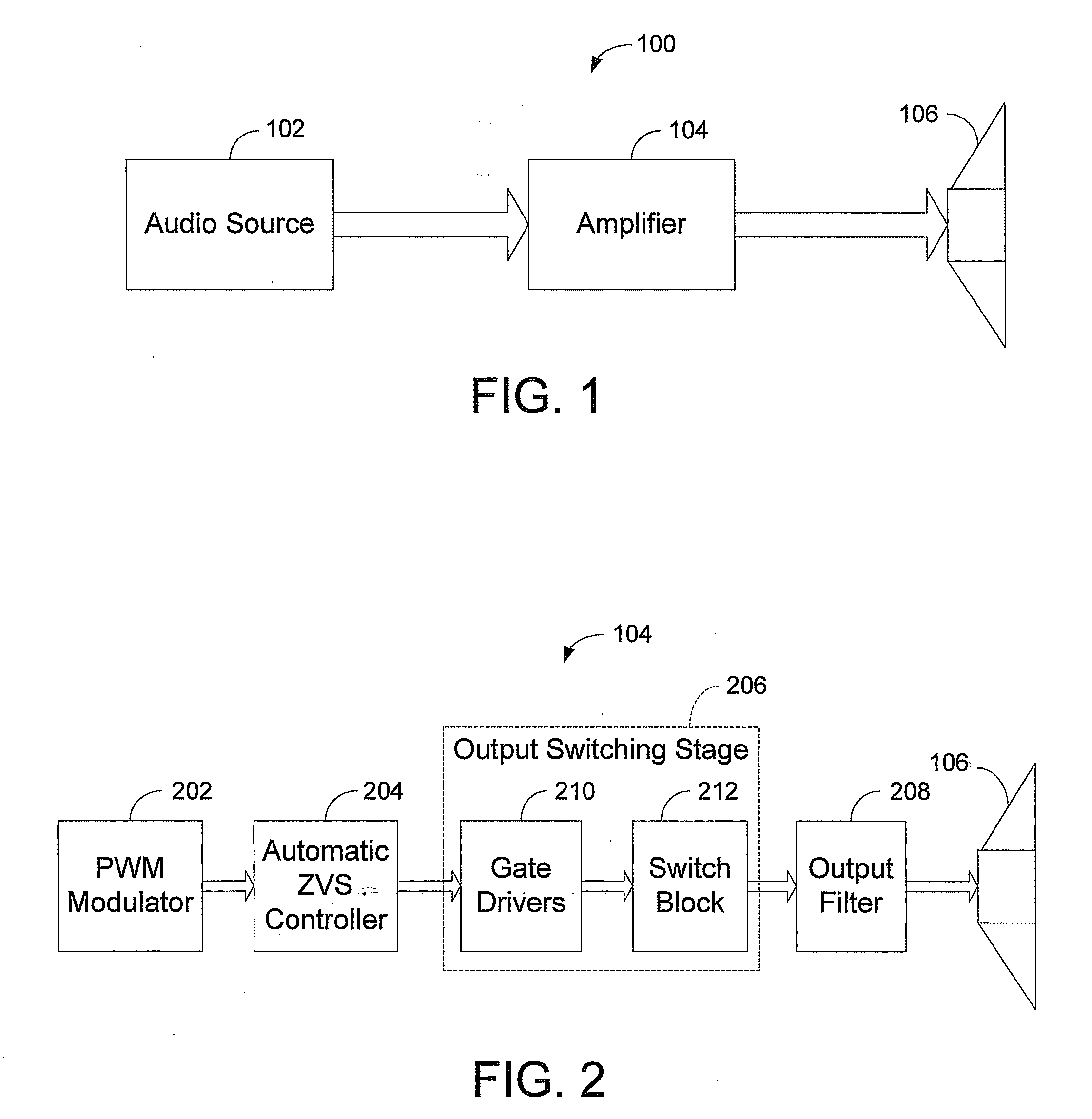
[0022]FIG. 1 is a block diagram of an example audio system 100 that includes an audio source 102, an audio amplifier 104, and a load 106. Audio source 102 may provide an input audio signal to the audio amplifier 104. The audio amplifier 104 may operate as DC to AC power converter to amplify the input audio signal using DC supply voltages. In other examples, the audio source 102 may be any other source providing an input signal to be amplified, and the audio amplifier 104 may be a power amplifier or any other form of DC to AC power converter capable of amplifying an input signal. The audio amplifier 104 may produce an amplified modulating output signal that is provided to the load 106. The load 106 may be one or more loudspeakers, or any other device capable of receiving an amplified output signal.

[0023]FIG. 2 is a block diagram of an example audio amplifier 104 and the load 106. The audio amplifier 104 includes a pulse width modulation (PWM) modulator 202, an automatic zero voltage ...


PUM


Abstract

A switching DC to AC power converter includes an automatic zero voltage switching (ZVS) mode controller. The automatic zero voltage switching mode controller may adjust a ZVS dead-time in accordance with a range of load currents being supplied by the power converter that range from quiescent conditions to a predetermined loading level of the power converter. The variable ZVS dead-time may be larger nearer to quiescent conditions, and become progressively smaller as load currents increase. Outside a predetermined range of load currents, the variable ZVS dead-time may be disabled or minimized.

Description

PRIORITY CLAIM [0001]This application claims the benefit of priority from U.S. Provisional Application No. 60 / 928,051, filed May 7, 2007, which is incorporated by reference.BACKGROUND OF THE INVENTION[0002]1. Technical Field[0003]The invention relates to zero voltage switching in power converters used in power conversion applications.[0004]2. Related Art[0005]A class D power converter may be used in switch-mode audio amplifiers. Class D signal amplifiers have been popular is recent years in audio applications due to advantages over legacy amplifiers. Less efficient amplifiers include Class A, Class B, Class AB, and Class H.[0006]Class A amplifiers replicate and amplify the entire input signal, and therefore, are very linear. Consequently, they are typically inefficient. Even the most efficient theoretical Class A amplifier can operate at only about 50% efficiency. In general, for every watt of power output capability by a Class A amplifier, another watt is wasted as heat. Actual eff...

Claims


Application Information

Patent Timeline
Patent Type & Authority Applications(United States)
IPC IPC(8): H02M7/44H02M1/00
CPCH02M7/48H02M2001/0012H03F3/217H02M1/0012
Inventor STANLEY, GERALD R.
Owner HARMAN INT IND INC
Learn More