Objective lens device, optical pickup device, optical-disc driving device and driving method of objective lens

a technology of optical pickup and optical pickup device, which is applied in the direction of optical beam source, record information storage, instruments, etc., can solve the problems of unsuitable configuration for reducing thickness and unnecessarily large beam effective diameter of optical system, and achieve the effect of reducing thickness and reducing the thickness of optical pickup devi

Inactive Publication Date: 2008-11-13
SONY CORP
View PDF14 Cites 13 Cited by
  • Summary
  • Abstract
  • Description
  • Claims
  • Application Information

AI Technical Summary

Benefits of technology

[0012]It has been found desirable to provide an objective lens device, an optical pickup device, and an optical-disc driving device, whereby the recording mediums of different three types of format can be handled, and reduction in thickness can be realized, and also a driving method of the objective lens thereof.
[0037]The optical pickup device may further include a prism including the first dichroic mirror and the second dichroic mirror, and a wavelength plate, which is provided in the prism, configured to change the polarization states of the first, second, and third laser beams. Particularly, the wavelength plate of the third laser beam is provided in the prism, which eliminates the necessity to provide a wavelength plate in the vicinity of the mirror which reflects the first laser beam. That is to say, for example, there is no need to secure the space of the wavelength plate for the first laser beam in the vicinity of the first objective lens, which contributes to reduction in the thickness of an optical pickup device.

Problems solved by technology

Consequently, the beam effective diameter necessary for the optical system becomes unnecessarily large as to DVD and BD of which the NA is greater, and in this point as well results in a configuration unsuitable for reduction in thickness.

Method used


Image

  • Objective lens device, optical pickup device, optical-disc driving device and driving method of objective lens
  • Objective lens device, optical pickup device, optical-disc driving device and driving method of objective lens
  • Objective lens device, optical pickup device, optical-disc driving device and driving method of objective lens

Examples


Embodiment Construction

[0071]Embodiments of the present invention will be described below with reference to the drawings.

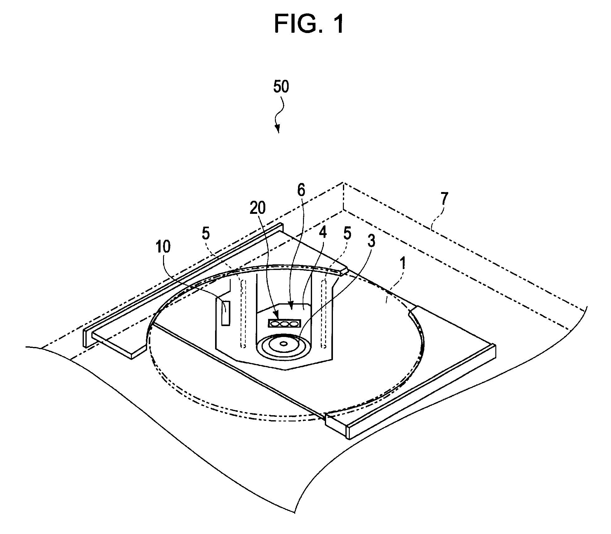
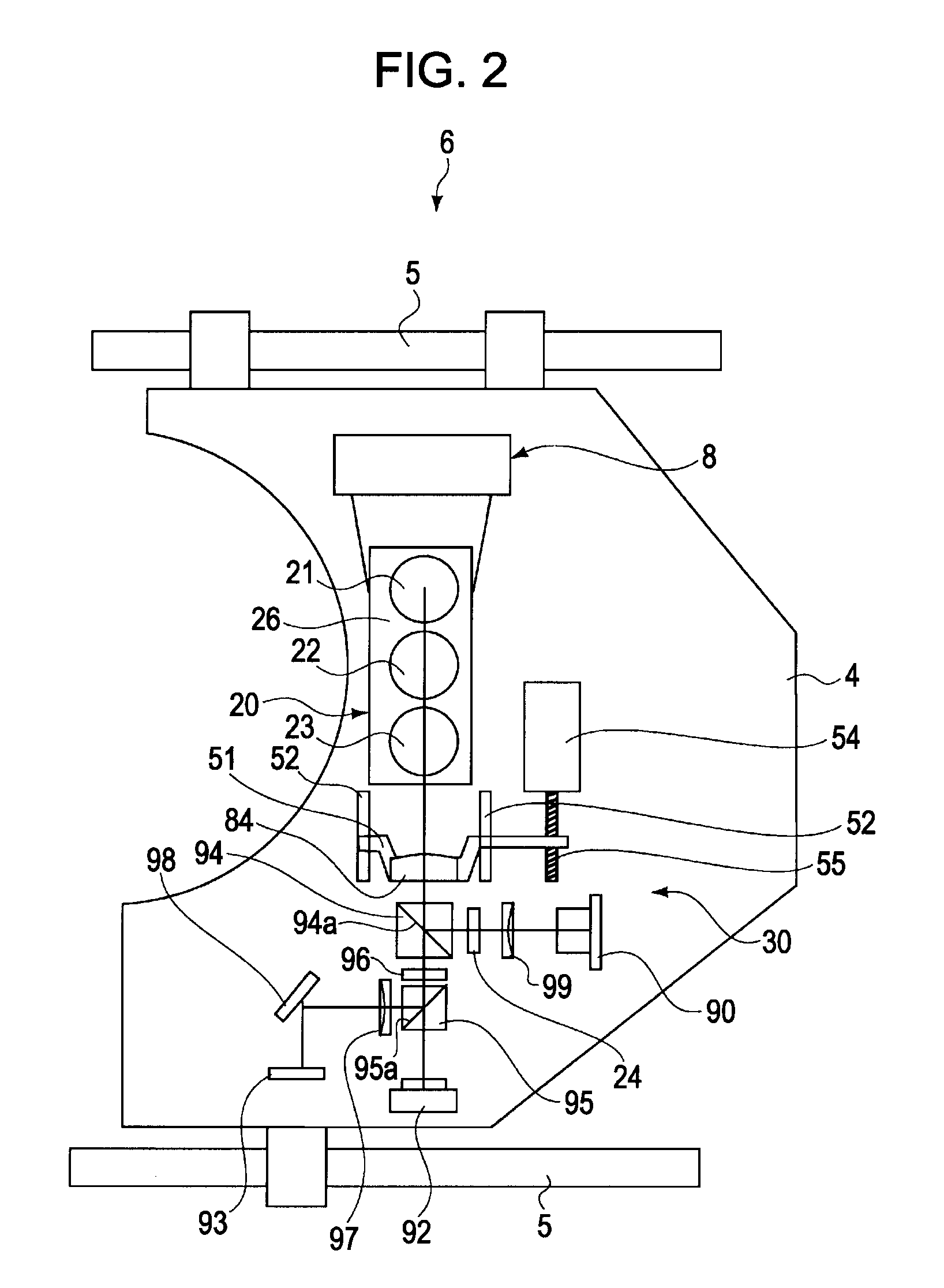
[0072]FIG. 1 is a schematic perspective view of an optical-disc driving device according to one embodiment of the present invention. FIG. 2 is a schematic plan view illustrating an optical pickup device implemented in the optical-disc driving device 50 in FIG. 1.

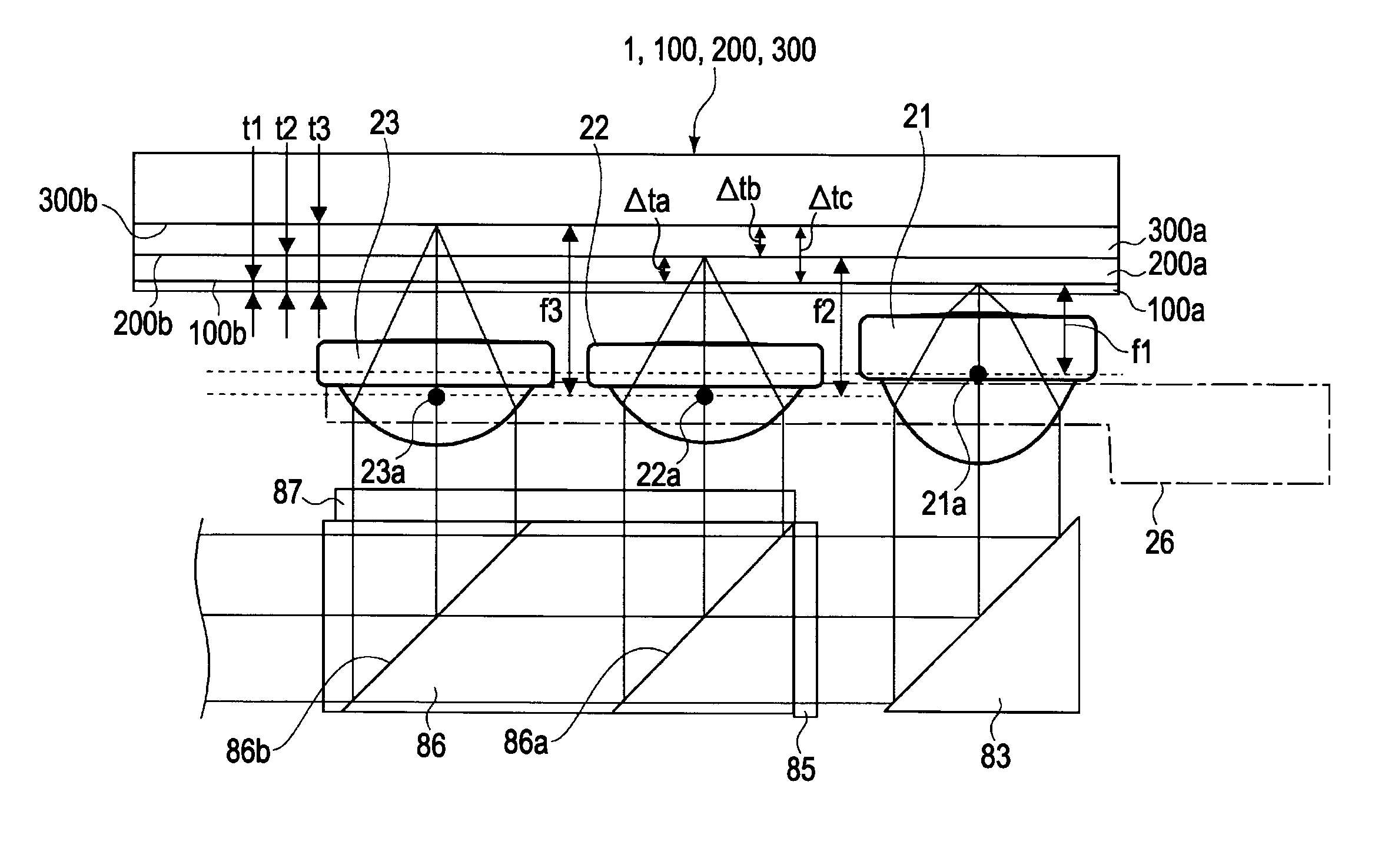
[0073]The optical-disc driving device 50 is a device configured to subject an optical disc (CD, CD-ROM, CD-R / RW, DVD, DVD-ROM, DVD±R / RW, DVD-RAM, BD, BD-ROM, BD-R / RE, HD DVD, etc.) 1 serving as an optical recording medium to recording / playback of information. The optical disc 1 may include a single signal recording layer, or may include multiple signal recording layers. Hereafter, the optical disc 1 will in some cases be referred to as “BD100”, “DVD200”, or CD300, and in some cases these three optical discs (or four optical discs including an optical disc such as HD DVD or the like) will be collectively referred to as an “optica...


PUM

PropertyMeasurementUnit
working distanceaaaaaaaaaa
wavelengthaaaaaaaaaa

Abstract

An objective lens device includes: a first objective lens having a first numerical aperture, which can condense light into a disc-shaped first optical recording medium including a first cover layer of first thickness; a second objective lens having a second numerical aperture which is smaller than the first numerical aperture, which can condense light into a disc-shaped second optical recording medium including a second cover layer of second thickness which is thicker than the first thickness; a third objective lens having a third numerical aperture which is smaller than the second numerical aperture, which can condense light into a disc-shaped third optical recording medium including a third cover layer of third thickness which is thicker than the second thickness; and a lens holder configured to integrally hold the first, second, and third objective lenses.

Description

CROSS REFERENCES TO RELATED APPLICATIONS[0001]The present invention contains subject matter related to Japanese Patent Application JP 2007-123081 filed in the Japanese Patent Office on May 8, 2007, the entire contents of which are incorporated herein by reference.BACKGROUND OF THE INVENTION[0002]1. Field of the Invention[0003]The present invention relates to an optical pickup device configured to perform at least one operation of optically recording a signal in an optical recording medium and playing a recorded signal, and an objective lens device to be implemented therein, and a driving method of an objective lens.[0004]2. Description of the Related Art[0005]Heretofore, there have been the following objective lenses, as an objective lens implemented in an optical pickup compatible with three formats of BD (Blu-ray Disc®, DVD (Digital Versatile Disc), and CD (Compact Disc) (e.g., see Japanese Unexamined Patent Application Publication No. 2005-302163 (paragraphs [0060] and [0061], an...

Claims


Application Information

Patent Timeline
Patent Type & Authority Applications(United States)
IPC IPC(8): G11B7/00G02B7/14G11B7/12G11B7/125G11B7/135
CPCG02B7/021G02B7/023G11B7/0933G11B7/0935G11B7/121G11B7/123G11B7/1275G11B7/1374G11B7/22G11B2007/0006
Inventor NISHI, NORIAKIYAMAMOTO, KENJIMIYAGI, TAKAHIRONAKANO, FUMIAKI
Owner SONY CORP
Why Eureka
Try Eureka