Wave attenuator and security barrier system - connector

a technology of attenuator and security barrier, which is applied in the direction of piers, groynes, weapons, etc., can solve the problems of affecting the safety of the public, and the structure suffers from a lack of versatility, so as to achieve the effect of effective dissipation of wave energy, alleviating the destructive nature of waves, and easy construction

Inactive Publication Date: 2008-11-13
HALO MARITIME DEFENSE SYST INC
View PDF9 Cites 18 Cited by
  • Summary
  • Abstract
  • Description
  • Claims
  • Application Information

AI Technical Summary

Benefits of technology

[0008]The purpose of the present invention is to provide an apparatus and system that carries out effective dissipation of the energy of the wave or water motion and which system can be easily constructed in the ocean to alleviate the destructive nature of waves but can also, just as readily, be constructed and installed in a marina, harbor or other location where the movement of the water can be caused by the wake of a boat or normal water movement, including storms that may cause the water to rise to a destructive energy.

Problems solved by technology

The destructive force of water can be damaging to structures, cause erosion of land and also damage to boats or other craft that are caused to move by the force of the water motion as it hits other boats or structures.
The problem, therefore, is not limited to shore areas where the erosive effect is potentially damaging to the shore area but can be present in marinas, boat moorage areas or to any structure that abuts or is located in the near proximity to the water.
While often effective, such permanent structures suffer from a lack of versatility; that is, once constructed, they are permanent structures that cannot be easily moved to other locations where such protection is needed.

Method used


Image

  • Wave attenuator and security barrier system - connector
  • Wave attenuator and security barrier system - connector
  • Wave attenuator and security barrier system - connector

Examples


example 1

Effect of Ocean Unit on Wave Dissipation

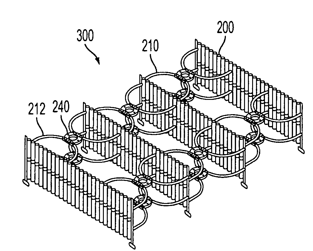
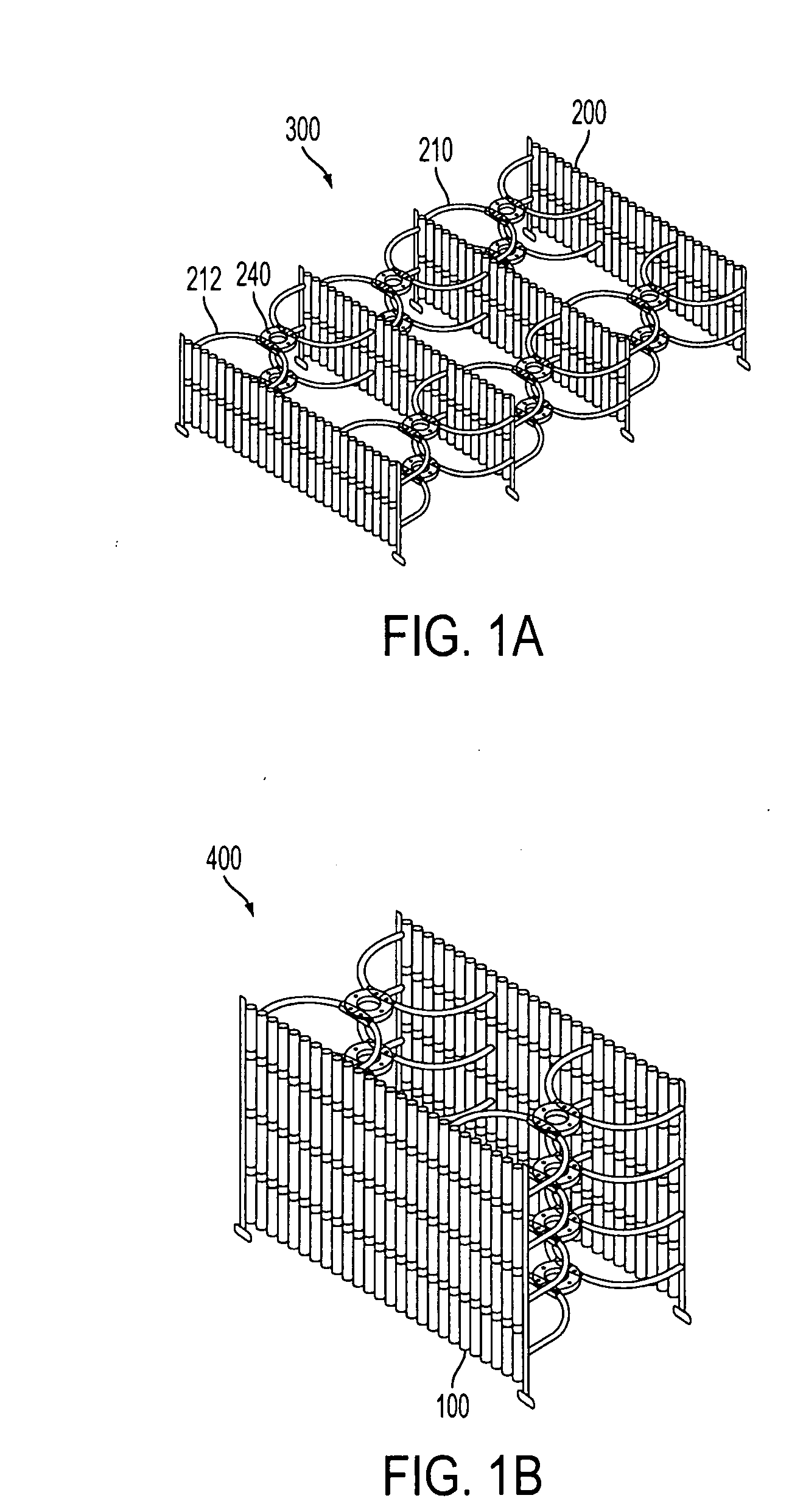
[0153]An ocean unit 300, such as that shown in FIG. 1A, was positioned in a facility with a water depth of 11 feet. The unit deployed had a width of 36 feet, and a draft of 8 feet. Waves having a height of about 3 feet, and periods ranging from about 4 to over 9 seconds, and wave lengths ranging from about 80 to over 430 feet, were tested. As shown in Table 2, a wave height reduction of between 50% to 75% was achieved with this embodiment.

TABLE 2Effects of wave length on wave dissipation.TransmissionHeightPeriodWave LengthCoefficientHeight(Feet)(Seconds)(Feet)(Kt)Reduction2.993.977.90.2575%3.135.2138.40.32867%2.896.5216.30.41259%2.87.9319.50.50350%2.989.2433.40.47652%

example 2

Effect of Larger Unit on Wave Dissipation

[0154]In this example, an embodiment comprising 8 rows of panels, having a length of about 78 feet, and an 8 foot draft, was moored in water having a depth of 12.5 feet. The wave heights ranged from about 3 to about 4 feet, with a periodicity of between about 4 to over 9 seconds, and a wave length of between about 80 to over 433 feet. As shown in Table 3, a wave height reduction of between 74 to 82% was achieved with this embodiment.

TABLE 3Effects of wave length on wave dissipation.TransmissionHeightPeriodWave LengthCoefficientHeight(Feet)(Seconds)(Feet)(Kt)Reduction2.963.977.90.18482%3.135.2138.40.23976%3.416.5216.30.21978%3.367.9319.50.24176%3.379.2433.40.26574%

[0155]Another embodiment is similar in structure to system 1400 (FIG. 7), but the panels include an inflatable bladder and at least one fin, both of which serve to adjust the energy of the wave passing through the panel. Panels including the bladder can be submerged or raised with wa...


PUM


Abstract

A connector for a wave attenuation system formed by connecting a plurality of panels in a structure positioned in a body of water; the system causes the dissipation of wave energy. Different configurations of panel, having different flow characteristics, used in the structure, and different types of connector used to connect panels, create different patterns of water flow within the structure, and contribute to wave energy dissipation. Units deployed in harbors, rivers, marinas and the like, help to prevent beach erosion and can facilitate beach nourishment. Embodiments can be utilized as a security barrier, preventing intrusion by trespassers, divers or various sized boats. A variety of sensors can be mounted to the structures, enabling detection of movement, chemical and biological agents, explosives or radiation. A submersible gate, comprising panels and a buoyancy control mechanism, allows for passage of boats and can be controlled remotely.

Description

CROSS REFERENCES TO RELATED APPLICATIONS[0001]This application claims the benefit of U.S. Provisional Patent Application Ser. Nos. 60 / 528,933, filed 11 Dec. 2003; 60 / 528,735, filed 11 Dec. 2003; and 60 / 528,936 filed 11 Dec. 2003, the contents of which are incorporated by reference herein.FIELD OF THE INVENTION[0002]Embodiments of the present invention relate to an apparatus, system and method to dissipate the energy of a wave or other like motion of water, and, in particular, to an apparatus and system that can be readily assembled on site and which provides for protection from the potentially damaging energy of the waves. Certain embodiments are designed to be used in locations such as a harbor, marina or inland waterway where there is a low wave energy environment. Additional embodiments function as security barriers to protect an area against intrusion by divers, trespassers, or various sized boats.BACKGROUND OF THE INVENTION[0003]The destructive force of water can be damaging to...

Claims


Application Information

Patent Timeline
Patent Type & Authority Applications(United States)
IPC IPC(8): E02B3/06E02B3/20E04BE04HF41H11/05F41H11/08F42D5/045
CPCE02B3/06E02B3/20F41H11/05F41H11/08F42D5/045Y02A10/00
Inventor BISHOP, JUSTIN
Owner HALO MARITIME DEFENSE SYST INC
Why Eureka
Try Eureka