Heated engine nose cone using spiral channels

Inactive Publication Date: 2008-11-13
HONEYWELL INT INC
View PDF5 Cites 39 Cited by
  • Summary
  • Abstract
  • Description
  • Claims
  • Application Information

AI Technical Summary

Problems solved by technology

Certain components of turbomachinery may be subjected to a flow of cold, moisture laden air which may produce an undesirable formation of ice.
In these prior art deicing systems, engine performance is diminished.
When energy is consumed in the production of bleed air or electrical heating it is not available to produce forward thrust for aircraft propulsion.
Nevertheless when engine oil flows through the prior-art de-icing systems, a high pressure drop may be produced in the oil flow.
This lengthy travel may produce a high pressure drop

Method used


Image

  • Heated engine nose cone using spiral channels
  • Heated engine nose cone using spiral channels
  • Heated engine nose cone using spiral channels

Examples


Embodiment Construction

[0019]The following detailed description is of the best currently contemplated modes of carrying out the invention. The description is not to be taken in a limiting sense, but is made merely for the purpose of illustrating the general principles of the invention, since the scope of the invention is best defined by the appended claims.

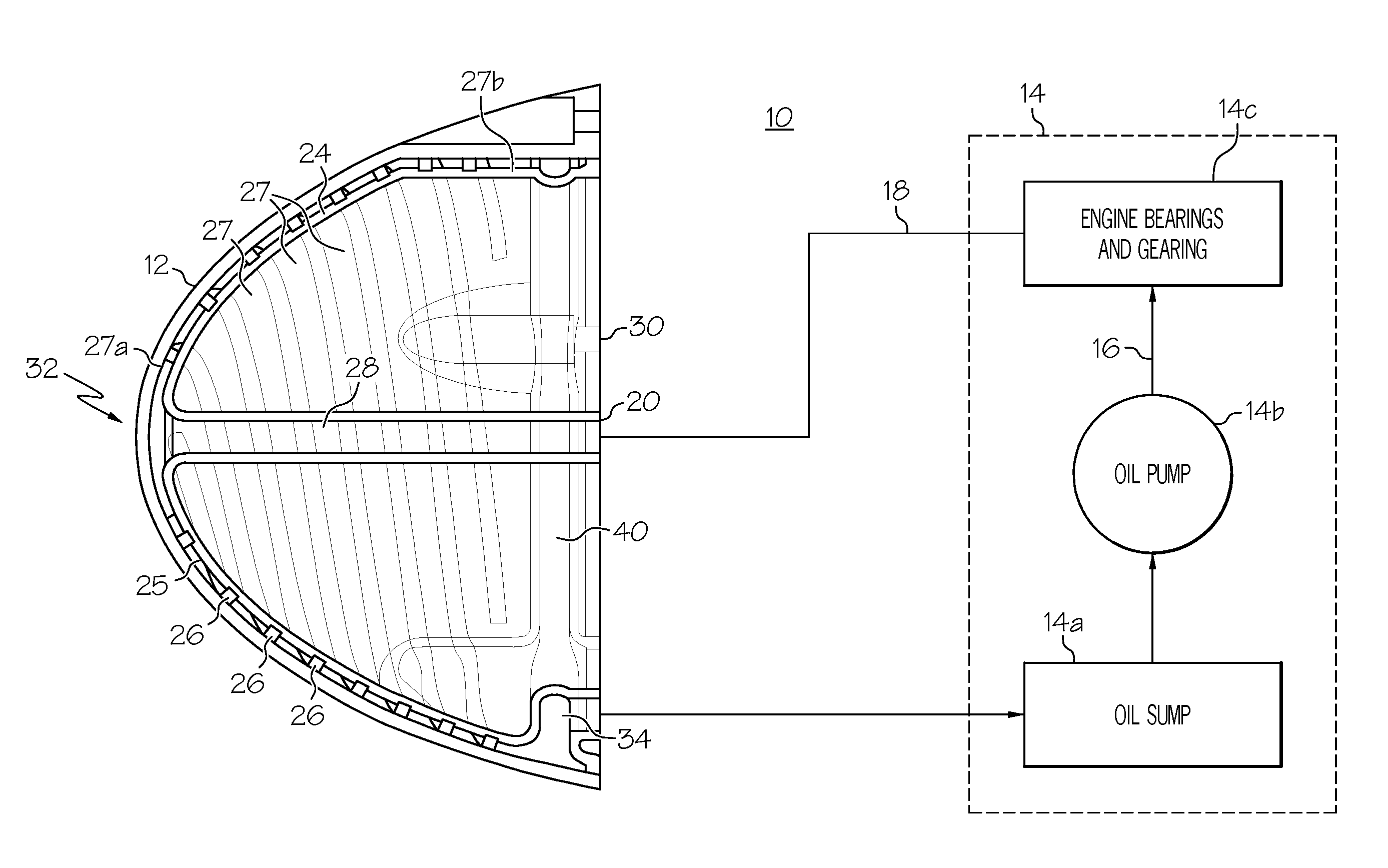
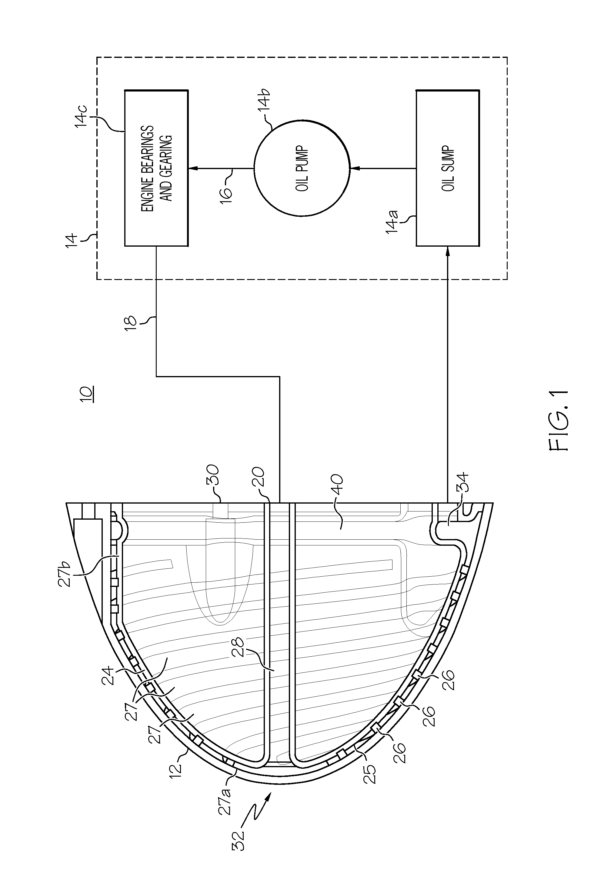
[0020]Broadly, the present invention may be useful for deicing or preventing ice formation on components of turbomachinery. More particularly, the present invention may provide a low-energy method for heating a nose cone of a turbine engine. The present invention may be particularly useful in vehicles such as aircraft in which ice formation on engine components may be problematic.

[0021]In contrast to prior-art de-icing systems, among other things, the present invention may provide heating with engine oil which produces only a small pressure drop of the engine oil as it passes through heat exchange passages. The present invention may, instead of serpenti...


PUM


Abstract

A nose cone of a turbomachine, such as an aircraft engine, is heated to prevent ice formation. The nose cone is configured as a conical shell positioned concentrically over an inner shell with a space therebetween. Spiral spacers in the space provide distributed passages through which heated lubricating oil flows. A system for separating entrained air from the lubricating oil as part of this mechanism is disclosed.

Description

CROSS REFERENCE TO RELATED APPLICATIONS[0001]This application claims the benefit of U.S. Provisional Application No. 60 / 917,591 filed May 11, 2007.BACKGROUND OF THE INVENTION[0002]The present invention is in the field of turbomachinery and, more particularly, turbomachinery which may be susceptible to surface icing with particular applications of aircraft propellers.[0003]Certain components of turbomachinery may be subjected to a flow of cold, moisture laden air which may produce an undesirable formation of ice. One example of such a component may be a nose cone of an engine of an aircraft. To counteract formation of ice, nose cones may be provided with integral heating systems.[0004]Various heating systems have been described in the prior art. An electrical heating system is described in U.S. Pat. No. 6,503,056 (Eccles et al. Jan. 7, 2003). In this system an engine is provided with an integral generator that may produce power to energize an electric heater in a nose fairing of an a...

Claims


Application Information

Patent Timeline
IPC IPC(8): F01D25/02F01D5/08F01D25/10F02C7/047
CPCF01D5/08F01D25/02F01D25/10F02C7/047Y02T50/671Y02T50/676Y02T50/60
Inventor JENSEN, JOSEPH M.BOLLA, JAMES D.HUMPHREY, JOSEPH T.NGUYEN, STEVE H.
Owner HONEYWELL INT INC
Why Eureka
Try Eureka