Reactive Spray Formation of Coatings and Powders

a technology of reactive spray and coating, applied in the direction of coating, plasma technique, metal material coating process, etc., can solve the problem of poor adhesion of powdery particles and agglomeration of particles

Inactive Publication Date: 2008-11-13
NAT RES COUNCIL OF CANADA
View PDF15 Cites 21 Cited by
  • Summary
  • Abstract
  • Description
  • Claims
  • Application Information

AI Technical Summary

Problems solved by technology

In addition, some techniques feed the precursors to the combustion nozzle as an aerosol and the combustion nozzle is not used in the atomization process.
A powdery agglomeration of particles with poor adhesion occurs if the gap between the nozzle and the substrate is too large.

Method used


Image

  • Reactive Spray Formation of Coatings and Powders
  • Reactive Spray Formation of Coatings and Powders
  • Reactive Spray Formation of Coatings and Powders

Examples


example 1

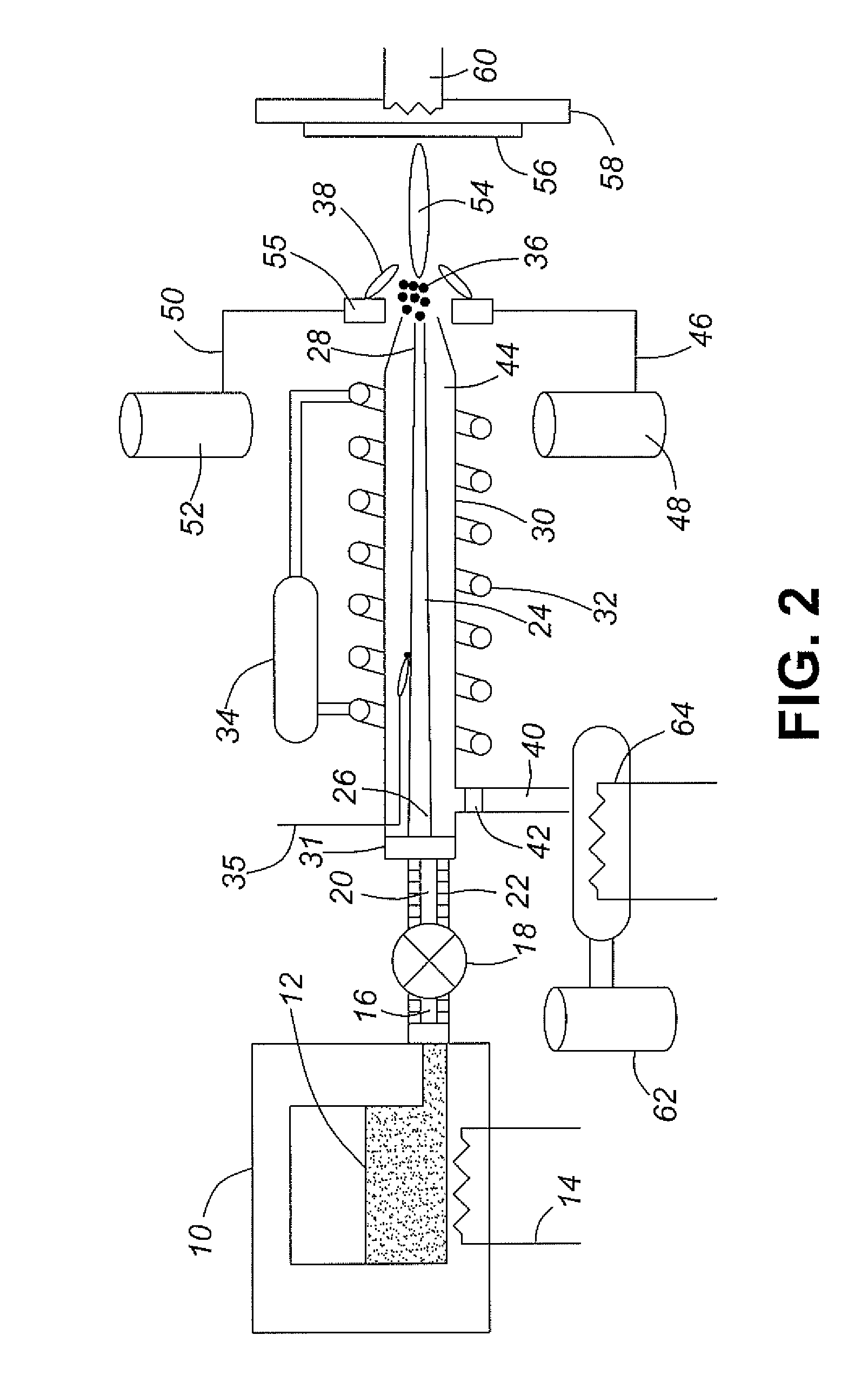
[0100]In Example 1, deposition of SDC was carried out on the apparatus as illustrated in FIG. 2. Two feedstock solutions were made. The first one was prepared with 0.46 g of samarium acetylacetonate (Sm-acac) and 4.67 g of cerium-2 ethylhexanoate (Ce-2eh) dissolved into 47.5 g of toluene in a container 10. Next, 215.3 grams of acetone were added to the container 10 and the container was capped off; then 112.6 g of di-methyl ether was added to the container and thoroughly shaken. The container was heated to 350 C. so that the solution formed a supercritical solution. The second solution was made exactly the same as the first but without Sm-acac and Ce-2eh and was designated as blank. The blank was stored in a separate container 10. The pump was set to a flow rate of 4 ml / min and the blank solution was passed into the nozzle. The frequency of the induction heater 32 was set to 271 kHz and the nozzle temperature 35 was set to 350 C. The oxidant 50 and fuel gas 46 for the burner assembl...

example 2

[0101]In Example 2, a bilayer of Pt and Pt / carbon for use in PEM fuel cells was deposited by RSDT. First, 0.75 g of Pt-acetylacetonate was dissolved in 197.6 g of toluene in a container 10. Next, 39.5 g of propane was added and the container was thoroughly mixed. The solution 12 was heated to 350 C. The substrate 56 (FIG. 4) in this example was a Nafion® membrane. In this example, a set of air knives 72 was used to cool the flame 54 so that the substrate 56 was maintained below 140 C. The reaction plume consisted initially only of streams 54 and 72 for the initial deposition of the Pt sublayer 90 onto the Nafion® membrane 56. The flow rate of the Pt feedstock was set to 4 ml / min. The frequency of the induction heater was set to 271 kHz and the nozzle temperature 35 was set to 200 C. The oxidant 46 and fuel gas 50 for the burner assembly were oxygen and methane respectively. The shaping gas 40 was set to a flow rate of 1.95 L / min and heated to a temperature of 350 C. The methane 50 a...


PUM

PropertyMeasurementUnit
diameteraaaaaaaaaa
inner diameteraaaaaaaaaa

Abstract

An apparatus and method for open-atmosphere flame based spraying employs a nozzle to preheat, pressurize and atomize a mechanically pumped reactive and flammable liquid solution through a small orifice or a nozzle and then a set of pilot flames to combust the spray. The liquid feedstock is preheated to a supercritical temperature before reaching the nozzle and is pressurized before spraying due to a reduced size of the outlet port of the feedstock flow channel relative to the inlet. A supplementary collimating, or sheathing, gas is supplied to the flow channel of the feedstock and both the feedstock and the supplementary gas are uniformly heated before spraying. This arrangement helps to avoid clogging of the nozzle and results in satisfactory control of the properties of the particulate products of the spraying procedure.

Description

FIELD OF THE INVENTION[0001]This invention, termed for identification purposes Reactive Spray Deposition Technology (RSDT), relates to the deposition of coatings and to the formation of powders, usually of particle size in the nanometer range, by atomizing a reactive liquid feedstock comprising flammable components. In particular, RSDT is an open atmosphere flame based spray technique that uses a nozzle to atomize a mechanically pumped liquid solution through a small orifice and then a set of pilot flames to combust the spray.BACKGROUND ART[0002]Reactive Spray Deposition Technology falls into a subset of deposition processes known collectively as thermal spraying. Thermal spraying and plasma spraying are both common deposition techniques used in the production of materials with controlled microstructure. Plasma spraying traditionally involves passage of a solid powder through or into a DC or AC plasma, subsequent melting of the solid particles and splats of material deposited on the...

Claims


Application Information

Patent Timeline
Patent Type & Authority Applications(United States)
IPC IPC(8): B05D1/08B05C11/00
CPCC23C4/121B05B7/208B05B7/166B05B7/1646C23C4/123B05B7/20B05B7/24B05B17/04C23C4/129
Inventor MARIC, RADENKAVANDERHOEK, THOMAS P.K.ROLLER, JUSTIN MICHAEL
Owner NAT RES COUNCIL OF CANADA
Why Eureka
Try Eureka