

Electronic blasting with high accuracy
a technology of electronic blasting and high accuracy, applied in the field of blasting, can solve the problems of increased rock fragmentation, time delays no better than 1 ms, unwanted ground vibration, etc., and achieve the effect of improving accuracy
- Summary
- Abstract
- Description
- Claims
- Application Information
AI Technical Summary
Benefits of technology
Problems solved by technology
Method used
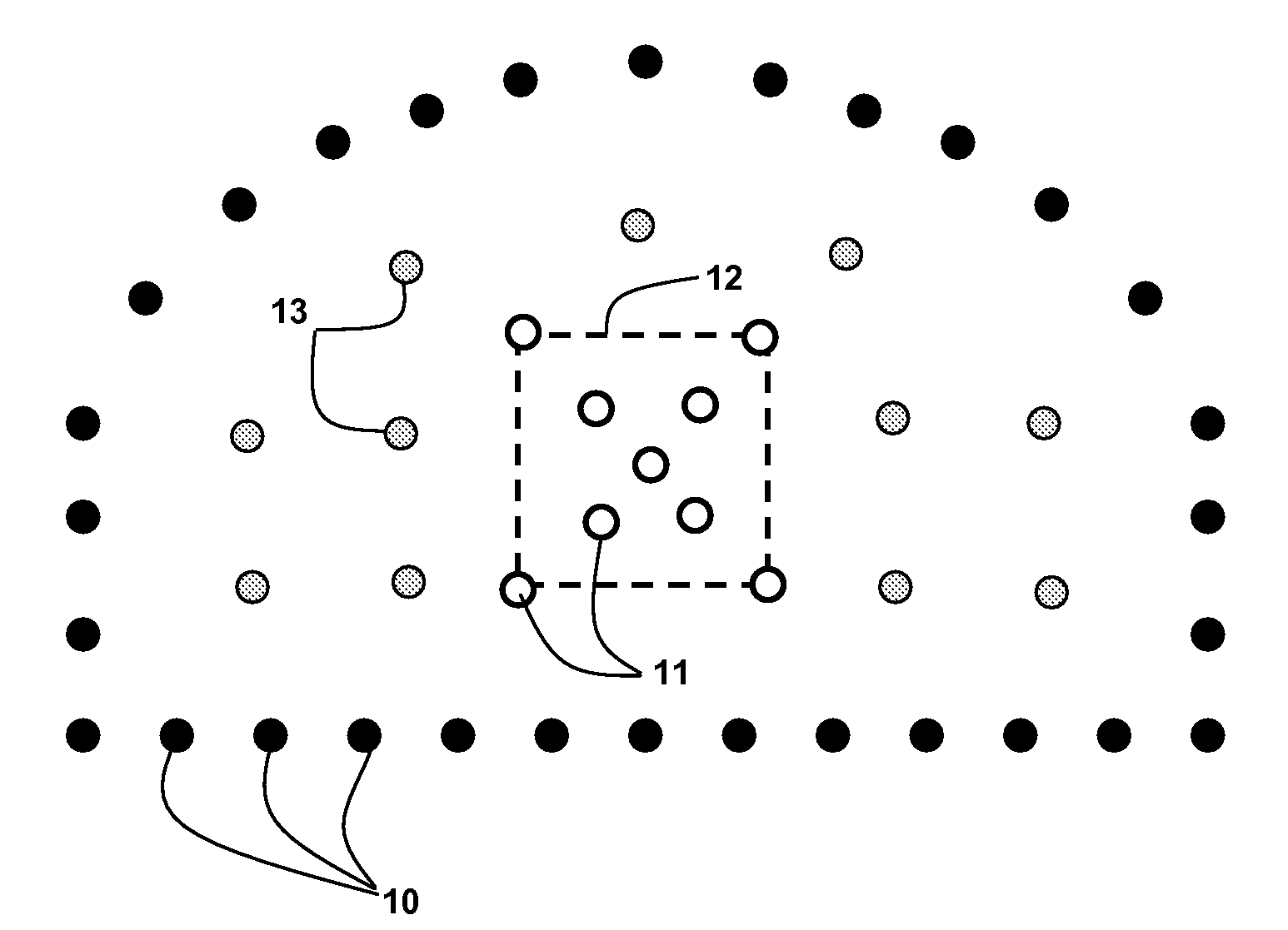
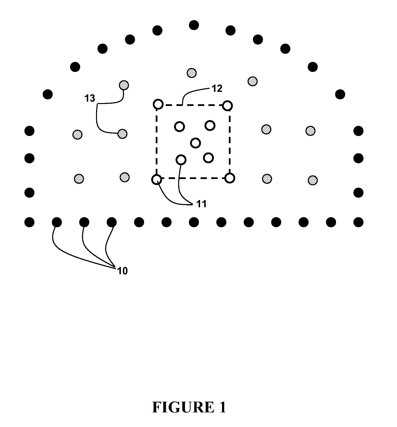
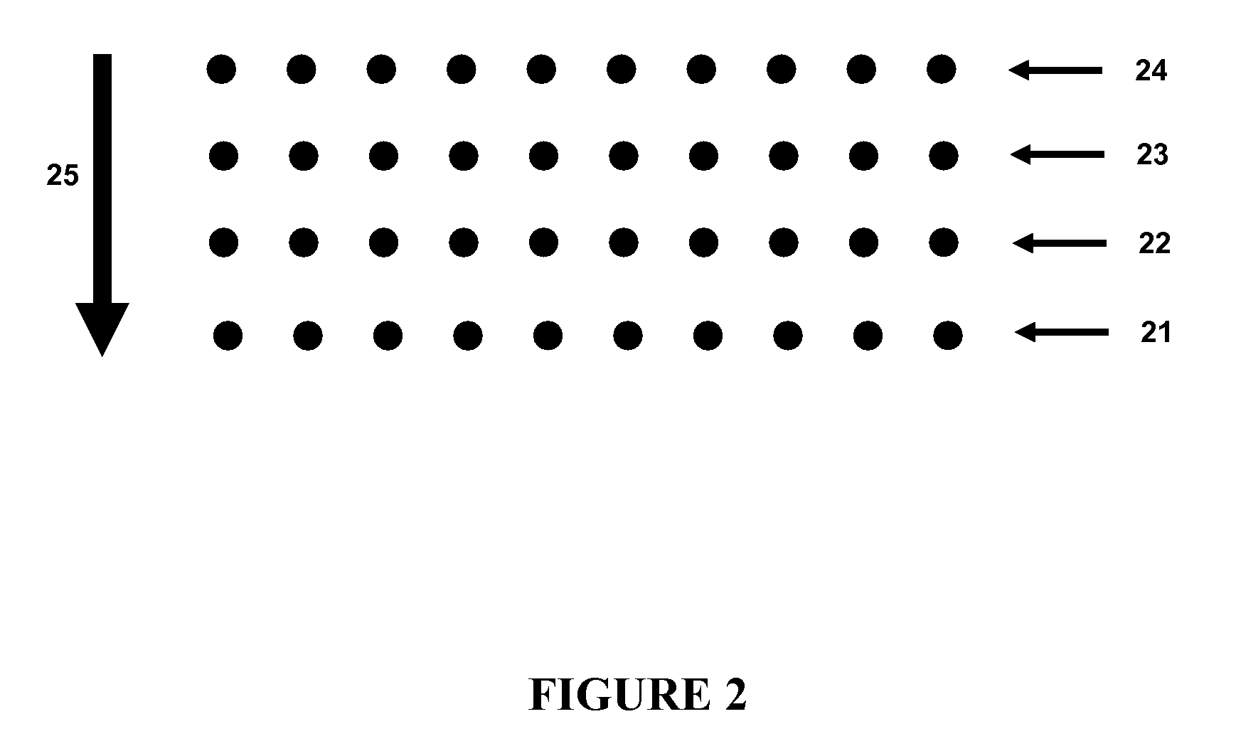
Image

Examples
example 1
Blasting Apparatus with High Accuracy
[0106]In one preferred embodiment of the invention there is provided a blasting apparatus for executing a blast plan for at least two detonators each programmable with a blasting delay time selectable to an accuracy of about 0.1 ms or better. In this embodiment the blasting apparatus comprises: at least one blasting machine for communicating at least one command signal to at least two associated detonators, wherein the command signal(s) may include at least including a FIRE signal to fire or initiate the detonators. The blasting apparatus may comprise: at least two detonators, each comprising:
[0107]i) a base charge;
[0108]ii) a firing circuit selectively connectable to the base charge;
[0109]iii) energy storage means for storing energy for initiation of the base charge via the firing circuit;
[0110]iv) an oscillator having a fixed and stable or calibratable frequency of at least about 10 kHz;
[0111]v) memory means for storing a delay time correspondi...
example 2
Detonator with High Accuracy Timing of Delay Time Actuation
[0118]In other embodiments, the invention also encompasses detonators or detonator assemblies for use as a component of the blasting apparatuses previously described. Such detonators or detonator assemblies are programmable to an accuracy of about 0.1 ms or better, and may comprise:
[0119]i) a base charge;
[0120]ii) a firing circuit selectively connectable to the base charge;
[0121]iii) energy storage means for storing energy for initiation of the base charge via the firing circuit;
[0122]iv) an oscillator having a fixed and stable or calibratable frequency of at least about 10 kHz;
[0123]v) memory means for storing a delay time corresponding to a number of counts of the oscillator;
[0124]vi) a receiver for receiving the at least one command signal from an associated blasting machine.
[0125]As discussed, upon receipt by the receiver of the FIRE signal from an associated blasting machine, the oscillator commences a count down of the...
example 3
Method of Blasting with High Accuracy Timing of Detonator Actuation
[0126]The invention further encompasses various methods of blasting, either for mining and rock fragmentation, or for seismic prospecting, that generally involve the blasting apparatuses of the invention. For example, one preferred method involves the steps of:
[0127](1) providing a blasting apparatus of the invention;
[0128](2) placing the at least two detonators at the blast site each in association with an explosive charge;
[0129](3) programming the at least two detonators with delay times selectable to an accuracy of about 0.1 ms or better, the delay times being stored in each memory means as a number of counts for each corresponding oscillator;
[0130](4) transmitting a command signal to FIRE from each of the at least one blasting machine to the at least two detonators, thereby causing each oscillator to count down its respective number of counts upon completion of which an associated base charge is initiated;
[0131]w...
PUM
 Abstract
Description
Claims
Application Information