Method and Apparatus for Vacuum Foaming Refrigerator Cabinets

a refrigerator cabinet and vacuum foaming technology, applied in the field of foaming, can solve the problems of faulty cabinets or moulded objects, not very suitable foaming refrigerator cabinets, large foaming moulds, etc., and achieve the effect of improving the foam distribution and reducing the length of the working cycl

Inactive Publication Date: 2008-11-20
CRIOS
View PDF25 Cites 24 Cited by
  • Summary
  • Abstract
  • Description
  • Claims
  • Application Information

AI Technical Summary

Benefits of technology

[0013]The main object of this invention is to provide a method for vacuum foaming refrigerator cabinets, doors and the like, capable of improving the manufacturing process, and at the same time allowing the foaming and complete filling of the hollow walls of a cabinet, in a comparatively short period of time, while maintaining of balanced pressure conditions inside and outside the cabinet during the foaming step.
[0024]The use of vacuum, in the foaming of refrigerator cabinets and the like, not only allows the use of fast reactive polyurethane mixtures, as mentioned previously, but also helps to considerably reduce the length of the working cycle, and improves the distribution of the foam during expansion, particularly in cabinets and for moulds of complex design.

Problems solved by technology

Although the use of highly reactive or fast polyurethane mixtures makes it possible to reduce the cycle times in the foaming of refrigerator cabinets, or in the production of moulded articles, in practice this solution has proved to have several drawbacks; in general, it is not very suitable for foaming refrigerator cabinets, or for foaming moulds of large dimensions, or having particularly complex designs.
In fact, due to the excessive reactivity and polymerisation speed of the polyurethane mixture, the latter tends to rapidly increase its viscosity, and then to solidify before the foam has completely filled the walls of the cabinet or the cavity of the mould, resulting in the production of faulty cabinets or moulded articles.
For this and other reasons, the chemical solution has been considered to be greatly restrictive in the foaming of refrigerator cabinets, using conventional methods and equipment.
While the simple reduction of atmospheric pressure, or the simple suction of the air, on the one hand serves to remove the gases that develop inside a mould, also facilitating a certain distribution degree of the foam, when accomplished in this way it is not suitable for foaming refrigerator cabinets and freezers for domestic use or having complex designs, by means of highly reactive polyurethane mixtures.
In fact, creating a relatively reduced vacuum, inside the two half shells which form the side walls of a refrigerator cabinet, would tend to deform them, causing them to bent inwards; the use of spacers or thrust members inside the walls of a cabinet, in addition to not completely solving the problem, would further complicate the manufacturing process.

Method used


Image

  • Method and Apparatus for Vacuum Foaming Refrigerator Cabinets
  • Method and Apparatus for Vacuum Foaming Refrigerator Cabinets
  • Method and Apparatus for Vacuum Foaming Refrigerator Cabinets

Examples


Embodiment Construction

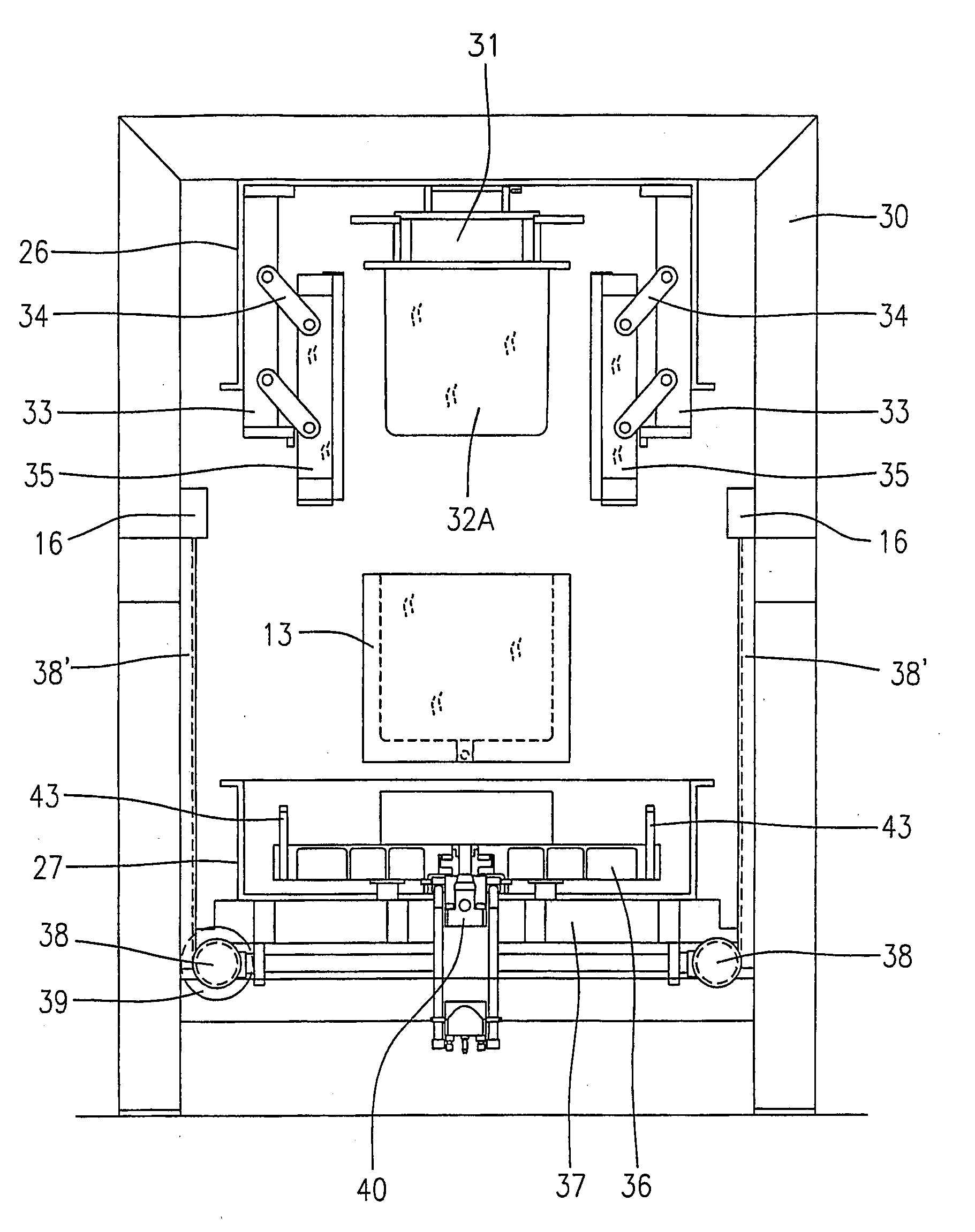
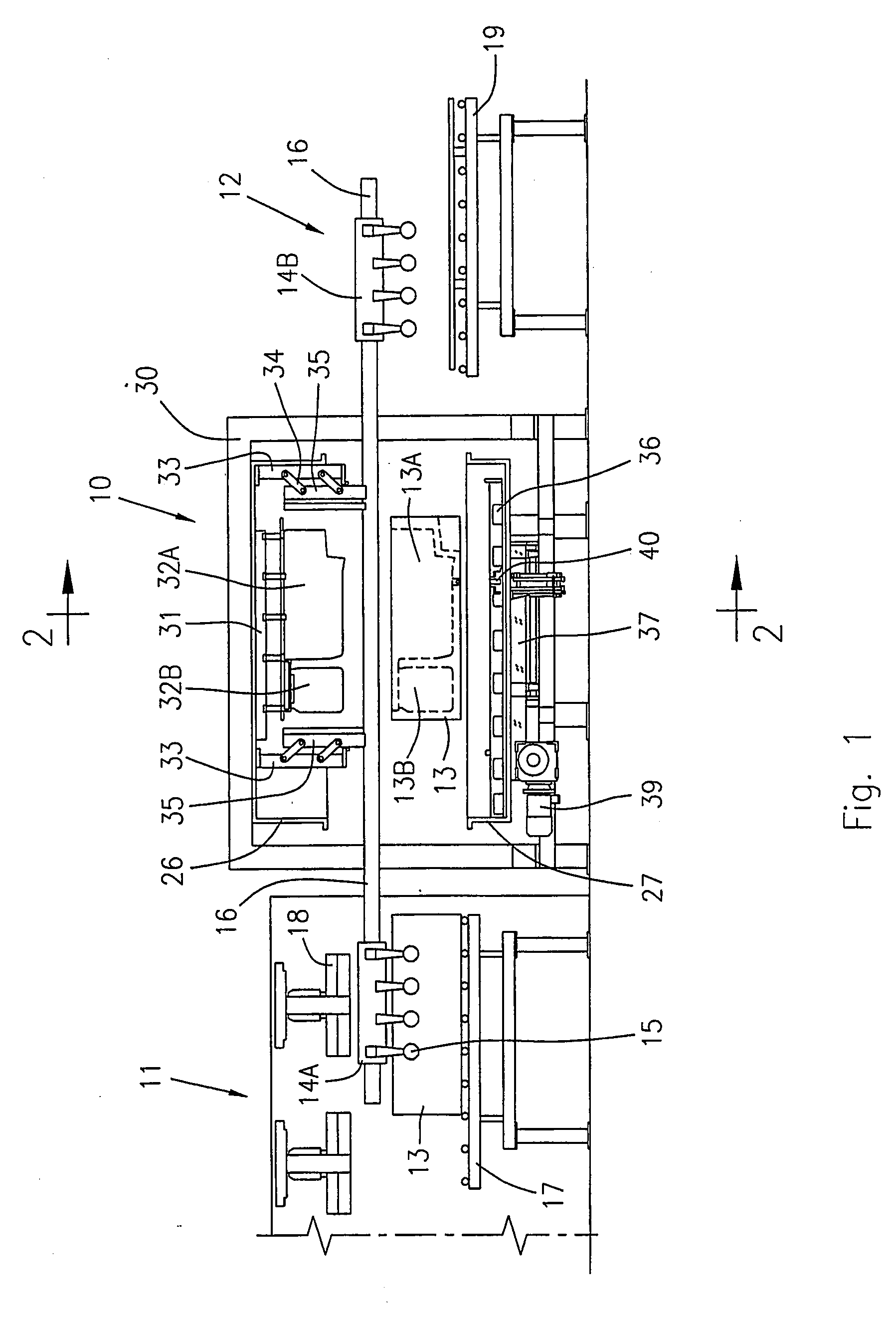
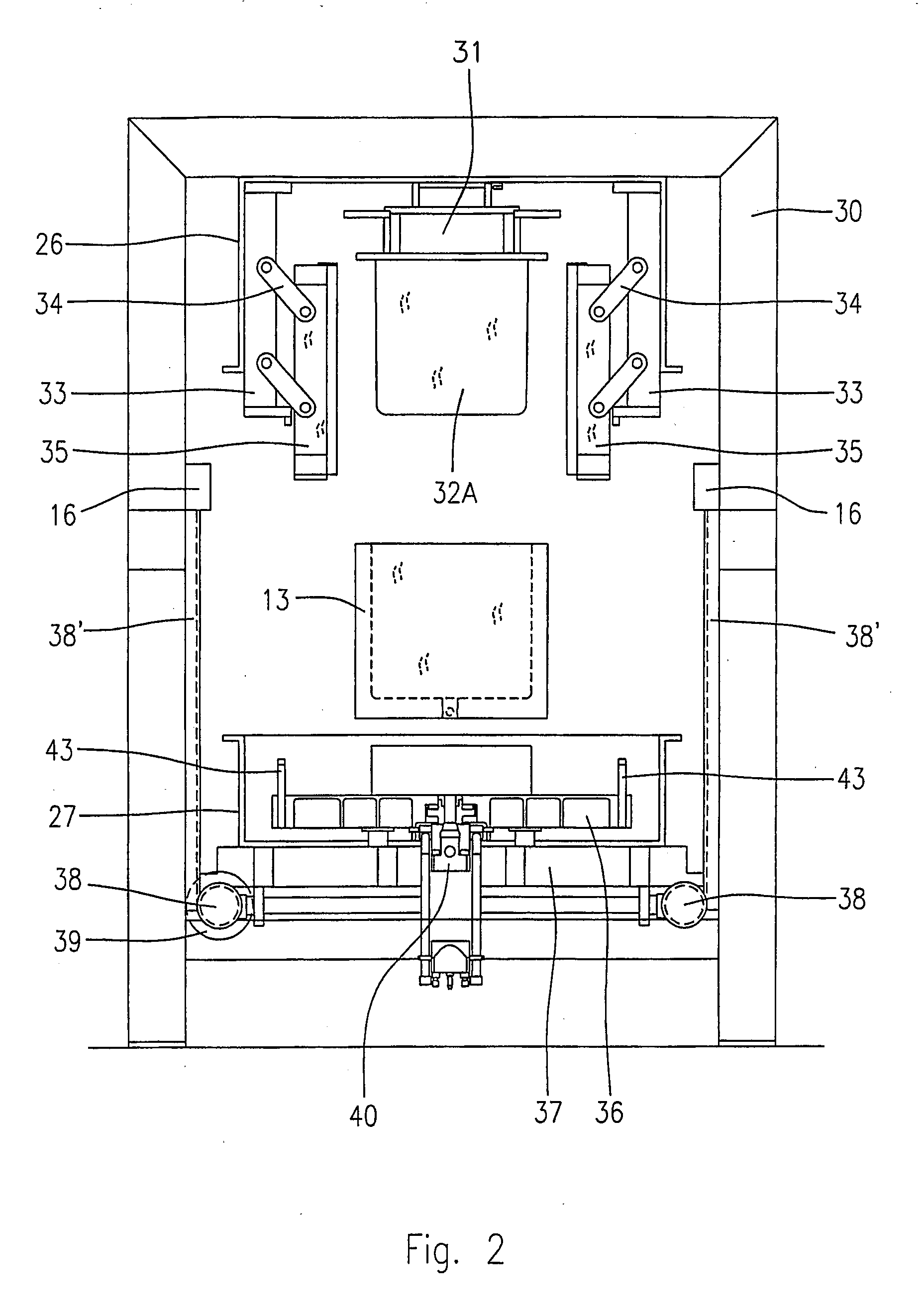
[0031]FIG. 1 shows a foaming apparatus for refrigerator cabinets under vacuum conditions, according to a possible embodiment of the invention.

[0032]As shown, in its more general form, the apparatus comprises a preheating station 11 for preheating the refrigerator cabinets 13, axially aligned to a foaming station 10, followed by a receiving station 12 from where the foamed cabinets are transferred towards a final foam curing area.

[0033]The refrigerator cabinets 13 can be moved from the preheating station 11 to the foaming station 10, and from the latter to the receiving station 12 in any suitable way. For example, it is possible to contemplate the use of one or more trolleys 14 provided with gripping members 15, for example sets of suction cups capable of grasping the cabinet 13 on two sides, as shown; the trolleys 14 are appropriately controlled to run along guide rails 16 which extend longitudinally between the work stations 11, 10 and 12.

[0034]The preheating station 11 and receivi...


PUM

PropertyMeasurementUnit
gel timeaaaaaaaaaa
thicknessesaaaaaaaaaa
vacuumaaaaaaaaaa

Abstract

A foaming jig (35) with a refrigerator cabinet (13) is enclosed in a vacuum chamber (25); a metered quantity of a polyurethane mixture is then fed into the hollow walls of the refrigerator cabinet (13), making the foam to growth by generating a vacuum degree in the vacuum chamber (25) and into the foaming jig (35); the foaming of the cabinet walls (13) can be carried out in a comparatively short time, by using fast reactive polyurethane formulations.

Description

BACKGROUND OF THE INVENTION[0001]This invention refers to the foaming of cabinets and / or doors for refrigerators, freezers and the like; in particular it is addressed to a method and to an apparatus for vacuum foaming, whereby it is possible to considerably accelerate the rising and the expansion step of the foam, ensuring a complete filling of the hollow walls of the cabinet and / or door within a comparatively short time.STATE OF THE ART[0002]The foaming of refrigerator cabinets is normally carried out by enclosing the cabinet in a jig suitable for counteracting the strong internal thrusts generated by the expansion of a polyurethane foam.[0003]Usually, a foaming jig comprises a bottom platen for supporting a cabinet to be foamed, four side platens movably supported towards and away from corresponding side walls of the cabinet, and a plug member shaped to penetrate into a compartment or compartments of the cabinet to withstand the internal thrusts of the polyurethane foam during exp...

Claims


Application Information

Patent Timeline
Patent Type & Authority Applications(United States)
IPC IPC(8): B29C44/42B29C44/34
CPCB29C44/3403B29C44/42B29C44/428
Inventor CORRADI, PIERO
Owner CRIOS
Why Eureka
Try Eureka