Apparatus and method for power added efficiency optimization of high amplification applications

a technology of efficiency optimization and amplifier, applied in the direction of rf amplifier, amplifier with semiconductor devices/discharge tubes, gain control, etc., can solve the problems of direct transfer of heat to heat, heat generation in amplifiers, waste, etc., to improve high-power amplifier applications, reduce thermal run away, and improve the effect of high-amplification conditions

Inactive Publication Date: 2008-11-20
ONQ TECH
View PDF3 Cites 14 Cited by
  • Summary
  • Abstract
  • Description
  • Claims
  • Application Information

AI Technical Summary

Benefits of technology

[0010]It is another optional feature and advantage of the present invention to provide an apparatus for improving high power amplifier applications.
[0011]It is yet another optional feature and advantage of the present invention to provide an apparatus capable of reducing the thermal run away associated with high amplification conditions.
[0012]The foregoing, and various other needs, are addressed, at least in part, by the present invention, wherein a power added efficiency tuner is used to dynamically monitor and control an amplifier output in order to maximize transfer efficiency from the input.
[0013]According to one embodiment of the invention, a power added efficiency optimizer apparatus is provided to maximize transfer efficiency for an amplified input signal. The apparatus includes a first coupling device that receives an input signal from an external source. The first coupling includes a first main path output and a first coupling branch. The first coupling device is constructed such that the first main path carries a large percentage of the input signal relative to the first coupling branch. A second coupling device receives an amplified input signal, and includes a second main path and a second coupling branch. The second coupling device is also configured such that it carries a large percentage of the amplified input signal relative to the second coupling branch. The apparatus also includes a variable load impedance for generating an impedance matched signal based on the amplified input signal, and a difference forming apparatus for generating a difference signal based on the input signal from the first coupling branch and the impedance matched signal. An efficiency tuner is also provided to process the output difference signal, and determine an optimum tuning command for the variable load impedance.
[0014]There has thus been outlined, rather broadly, the more important features of the invention and several, but not all, embodiments in order that the detailed description thereof that follows may be better understood, and in order that the present contribution to the art may be better appreciated. There are, of course, additional features of the invention that will be described hereinafter and which will form the subject matter of the claims appended hereto.
[0015]In this respect, before explaining at least one embodiment of the invention in detail, it is to be understood that the invention is not limited in its application to the details of construction and to the arrangements of the components set forth in the following description or illustrated in the drawings. The invention is capable of other embodiments and of being practiced and carried out in various ways. Also, it is to be understood that the phraseology and terminology employed herein are for the purpose of description and should not be regarded as limiting.

Problems solved by technology

In a high-power, high-frequency, and broad band amplifier application, thermal run away is one of the most difficult problems of the design.
Heat is generated in an amplifier due to inefficient transfer of power to the output stage.
Whatever is not converted by the transducer operation of the amplifier into transferred power, which for a communications system is DC to radio frequency (RF) power, is directly transferred to heat and wasted.

Method used


Image

  • Apparatus and method for power added efficiency optimization of high amplification applications
  • Apparatus and method for power added efficiency optimization of high amplification applications
  • Apparatus and method for power added efficiency optimization of high amplification applications

Examples


Embodiment Construction

[0026]Reference now will be made in detail to the presently preferred embodiments of the invention. Such embodiments are provided by way of explanation of the invention, which is not intended to be limited thereto. In fact, those of ordinary skill in the art may appreciate upon reading the present specification and viewing the present drawings that various modifications and variations can be made.

[0027]For example, features illustrated or described as part of one embodiment can be used on other embodiments to yield a still further embodiment. Additionally, certain features may be interchanged with similar devices or features not mentioned yet which perform the same or similar functions. It is therefore intended that such modifications and variations are included within the totality of the present invention.

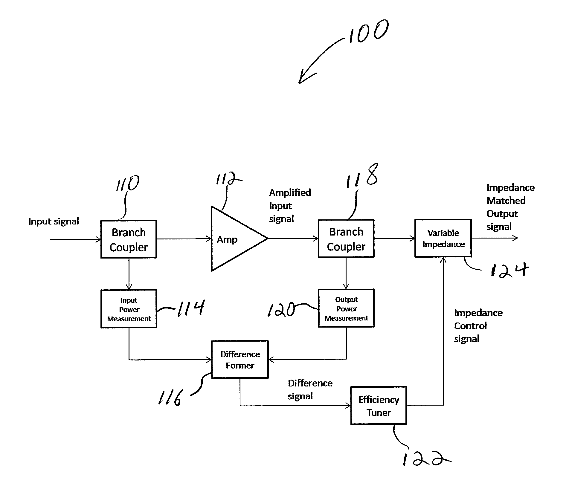
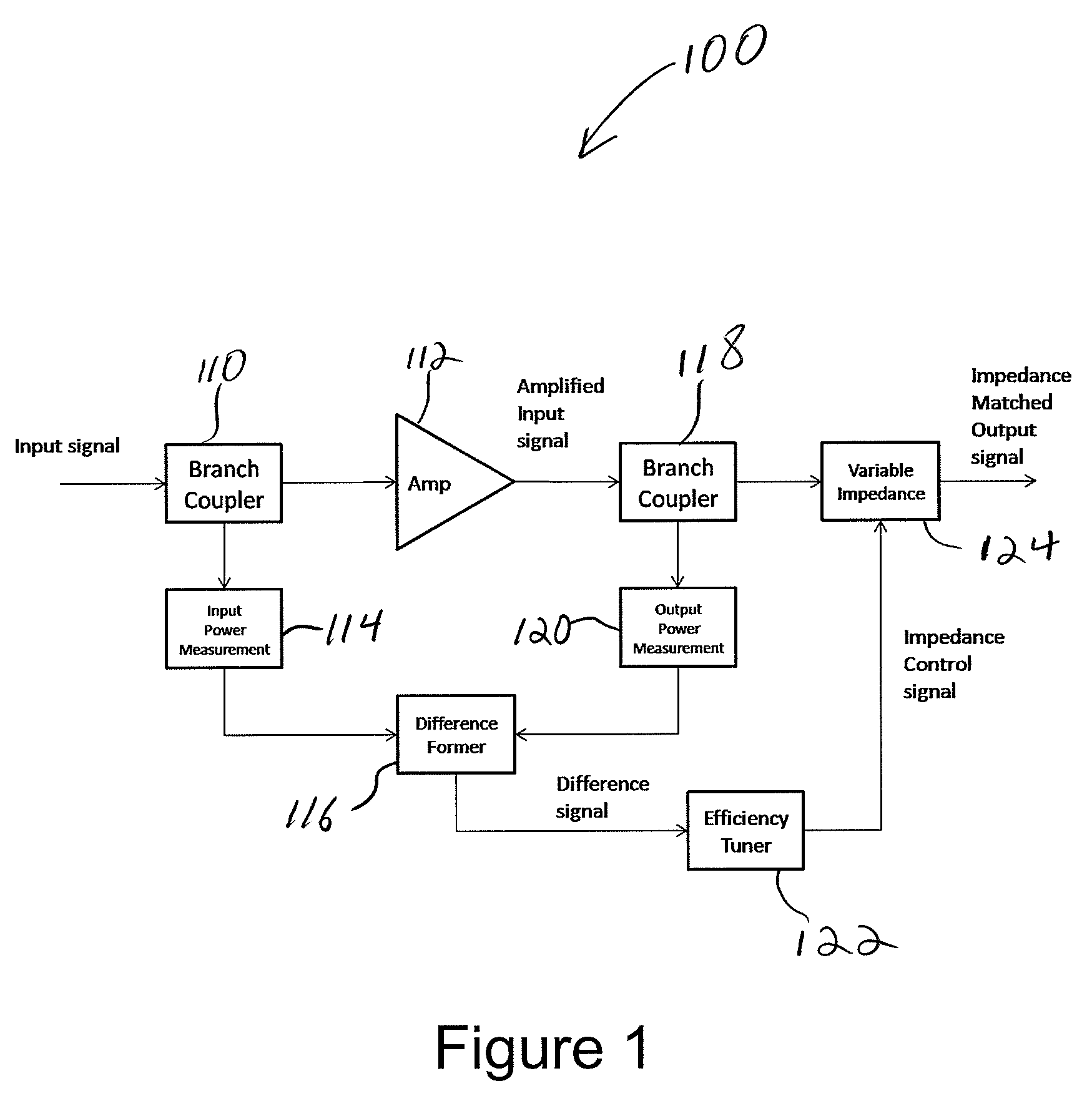
[0028]Referring to the drawings, and initially to FIG. 1, a power added efficiency apparatus 100 for improving transfer efficiency is illustrated. As shown in FIG. 1, an input sig...


PUM


Abstract

A power added efficiency optimizer apparatus is provided for measuring and monitoring input and output power of an amplifying device, and adjusting the load impedance seen by the amplifying device so that power added efficiency is maintained at optimum levels. A power added efficiency optimizing device includes a variable load impedance that can be controlled, at least one power detection device located after the load, a difference forming apparatus, and at least one coupling device. The power added efficiency optimizing device provides an ability to maintain an amplifier at peak efficiency in a dynamic way and in the presence of changing electromagnetic load conditions.

Description

CROSS REFERENCE TO RELATED APPLICATION[0001]This application claims priority from U.S. application Ser. No. 60 / 912,450, filed Apr. 18, 2007, the contents of which are incorporated herein by reference.BACKGROUND OF THE INVENTION[0002]1. Technical Field[0003]The present invention relates to high power amplification systems and, more particularly, to a power added efficiency optimizer capable of reducing thermal run away.[0004]2. Description of the Related Art[0005]In a high-power, high-frequency, and broad band amplifier application, thermal run away is one of the most difficult problems of the design. The thermal run away comes from self heating of a solid state device when used under amplifying conditions. Conventional solutions to this problem often involve development of adequate heat sinks from bulk conductive material to support the thermal conditions under which the device must operate. Heat is generated in an amplifier due to inefficient transfer of power to the output stage. ...

Claims


Application Information

Patent Timeline
Patent Type & Authority Applications(United States)
IPC IPC(8): H03F3/60
CPCH03F1/02H03F1/56H03F3/191H03F3/60H03F2200/228H03F2200/387H03F2200/393H03F2200/451H03F2200/99
Inventor ANDREWS, MICHAEL S.
Owner ONQ TECH
Why Eureka
Try Eureka