Image stabilization driving device

a driving device and image stabilization technology, applied in the direction of generator/motor, color television, television system, etc., can solve the problems of camera phone being prone to external vibration impact, blurry image, unrecognizable image, etc., to facilitate the application of electronic devices and facilitate assembly and manufacture

Inactive Publication Date: 2008-11-20
IND TECH RES INST
View PDF4 Cites 12 Cited by
  • Summary
  • Abstract
  • Description
  • Claims
  • Application Information

AI Technical Summary

Benefits of technology

[0017]As the image stabilization driving device provided by the present invention employs the SAW actuator and the contactless force action unit to integrate with and drive the slidable block. In contrast to the complicated structure and size in the prior art incorporating with a multi-layer metal frame and a piezoelectric actuator, the present invention certainly achieves the object of thin profile and simple parts ...

Problems solved by technology

Whereas, in view of the trend of miniaturization, camera phone is prone to the impact of external vibration, especially the one caused by hands, while taking a picture.
Such impact will introduce a bad quality of image taken, which makes the image blurry and unrecognizable.
However, from the design point of view, the mechanism still needs to be assembled from parts, and its assembly process and parts are diverse and complicated, so as to fail to meet the miniaturization requirement of modules.
As ...

Method used


Image

  • Image stabilization driving device
  • Image stabilization driving device
  • Image stabilization driving device

Examples


first preferred embodiment

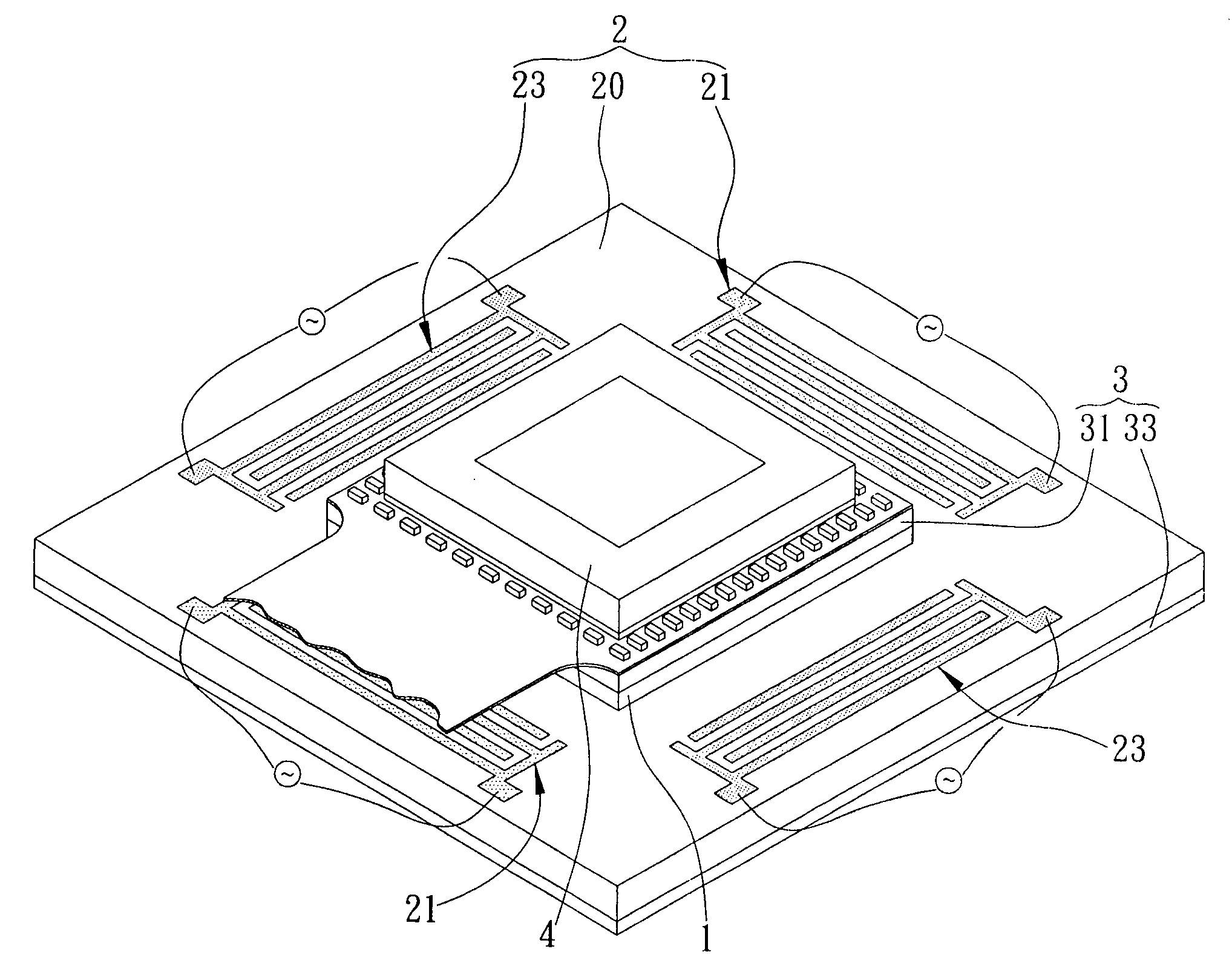
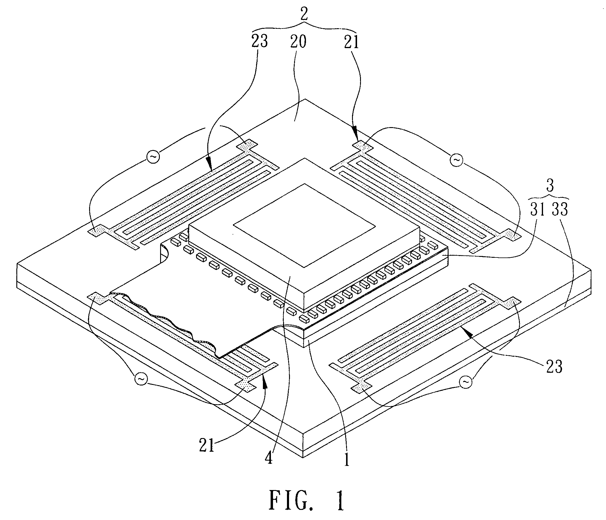
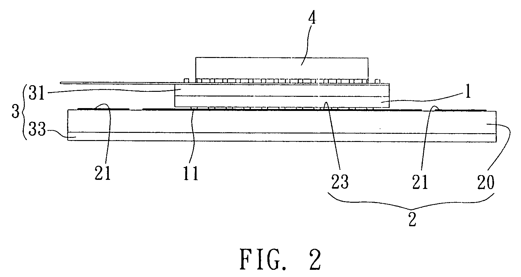
[0025]As shown in FIG. 1 and FIG. 2 illustrating the first preferred embodiment for the image stabilization driving device of the present invention, the image stabilization driving device serves to drive a planar movement of an image sensor 4. The image stabilization driving device includes a slidable block 1 coupled to the image sensor 4, a flat SAW actuator 2 driving the slidable block 1 to have a planar movement on a surface contacted therewith, and an contactless force action unit 3 providing a preload force for the slidable block 1 to contact with the flat SAW actuator 2, thereby achieving the object of thin profile and simple parts for the image stabilization driving device and overcoming the shortcoming of the prior art failing to attain thin profile and simple parts.

[0026]The slidable block 1 pertains to a flat-panel design, where its top side is integrated with the image sensor 4 of an optical system which is usually a CCD (Charge Coupled Device) or a CMOS while there is no...

second preferred embodiment

[0033]FIG. 5 and FIG. 6 are provided in accordance with the second preferred embodiment, in which components that are identical or similar to those in the aforementioned embodiment are expressed by identical or similar component symbols, and detailed description therefore is omitted to make the description of the present invention more clear and comprehensive. What the second preferred embodiment differs from the first preferred embodiment lies in that a flat SAW actuator in the first preferred embodiment and two orthogonal linear SAW actuators in the second preferred embodiment are adopted.

[0034]As shown in FIG. 5 and FIG. 6, the image stabilization driving device provided by the present embodiment includes a first slidable block la coupled to the image sensor 4; a first linear SAW actuator 2a carrying and contacting with the first slidable block 1a to drive a linear movement of the first slidable block la on a surface contacted therewith; a second slidable block 1b coupled to a bo...


PUM


Abstract

An image-stabilizing driving device is proposed, including a slidable block coupled to an image sensor, a flat surface acoustic wave actuator for contacting with and driving the slidable block to move on a surface contacted therewith, and a contactless force action unit having a first and a second contactless force action layers. The first contactless force action layer is formed between the slidable block and the image sensor and the second contactless force action layer is formed on a bottom surface of the flat surface acoustic wave actuator, thereby providing preload force for the slidable block to contact with flat surface ascoustic wave actuator so as to form a thin image-stabilizing driving device.

Description

FIELD OF THE INVENTION[0001]The present invention relates to a driving device, and more particularly to an image stabilization driving device for preventing image quality deterioration caused by shaking.BACKGROUND OF THE INVENTION[0002]Nowadays, due to the thickness limitation of the optical system concerned by mobile phone or camera, the structures of the optical system and the actuator are as simple as possible, and their sizes are as small as possible, so as to adapt these devices to the development trend of miniaturization or thin profile.[0003]A piezoelectric actuator has the advantages of small size, large output, low power consumption, silence and high compatibility, and thus is adopted by a digital camera or a camera phone to drive an optical lens therein, such that the optical lens functions to zoom in or zoom out, making it one of the critical techniques of optical systems or related products. Meanwhile, while camera phone is gradually replacing digital camera, user's dema...

Claims


Application Information

Patent Timeline
IPC IPC(8): H04N5/225H03H9/25
CPCH04N5/23248H04N5/23287H04N23/68H04N23/687
Inventor WU, WEN-IHU, CHAO-CHANGHO, TZONG-CHETSAI, MING-JYESHEN, SHENG-CHIH
Owner IND TECH RES INST
Why Eureka
Try Eureka