
RF Transmitter With Nonlinear Predistortion and Method Therefor

a nonlinear and transmitter technology, applied in the field of radiofrequency (rf) communication, can solve the problems of spectral regrowth, signal distortion resulting from nonlinear amplification, and the inability to provide linear amplification, etc., and achieve the effect of reducing the cost of rf transmitters

Inactive Publication Date: 2008-11-20
CRESTCOM INC
View PDF84 Cites 67 Cited by
  • Summary
  • Abstract
  • Description
  • Claims
  • Application Information

AI Technical Summary

Benefits of technology

[0012]It is an advantage of at least one embodiment of the present invention that an improved RF transmitter with nonlinear predistortion and a method therefor are provided.
[0013]Another advantage of at least one embodiment of the present invention is that the configuration of nonlinear energy intentionally generated for purposes of cancellation in response to the operation of a feedback control loop is improved.
[0014]Another advantage of at least one embodiment of the present invention is that nonlinear energy intentionally generated for purposes of cancellation is blocked at times when a power amplifier is unlikely to be producing nonlinear energy.

Problems solved by technology

RF transmitters that attempt to provide linear amplification may suffer from a variety of signal distortions.
In such applications, real-world RF amplifiers fail to provide perfectly linear amplification, causing spectral regrowth to occur.
Since modern regulations place strict limitations on the amount of spectral regrowth that may be tolerated, any signal distortion resulting from nonlinear amplification poses a serious problem for RF transmitter designs.
In addition, any linear distortion in the transmitted RF communication signal is undesirable because linear distortion must be overcome in a receiver, often by necessitating transmission at greater power levels than would otherwise be required.
Linear distortions may also complicate the spectral regrowth problem.
But as such techniques get more exotic, the analog component costs increase, and often increase dramatically.
Thus, many prior art RF transmitters restrict their operation to only the lower signal power levels.
But this is an undesirable approach because it requires the use of overly expensive power amplifiers for a given power level requirement, and it forces the power amplifiers to operate inefficiently.
Moreover, in many RF communication applications, including cellular basestations, cellular handsets, and other applications, transmission power levels may spend extended periods of time in the lower power ranges of the RF transmitter's capabilities.
These characteristics of typical RF transmitters with respect to the production of nonlinear energy pose challenges for a control system that attempts to track nonlinear energy production in an RF transmitter.
And, a control loop that is insensitive to noise is likely to do a poor job of tracking bursts of nonlinear energy interspersed with extended periods of little nonlinear energy.
For either scenario, nonlinear energy generated in response to the operation of the control loop is likely to be less accurately configured for purposes of cancellation than it could be.
Consequently, a collection of nonlinear signals is derived that accurately equates to the nonlinearity at an average signal magnitude, but that is less accurate than desired the vast majority of the time when the communication signal does not exhibit its average.
This causes the nonlinear cancellation energy to be less accurate than desired, and limits the effectiveness of the predistortion.

Method used


Image

  • RF Transmitter With Nonlinear Predistortion and Method Therefor
  • RF Transmitter With Nonlinear Predistortion and Method Therefor
  • RF Transmitter With Nonlinear Predistortion and Method Therefor

Examples


Embodiment Construction

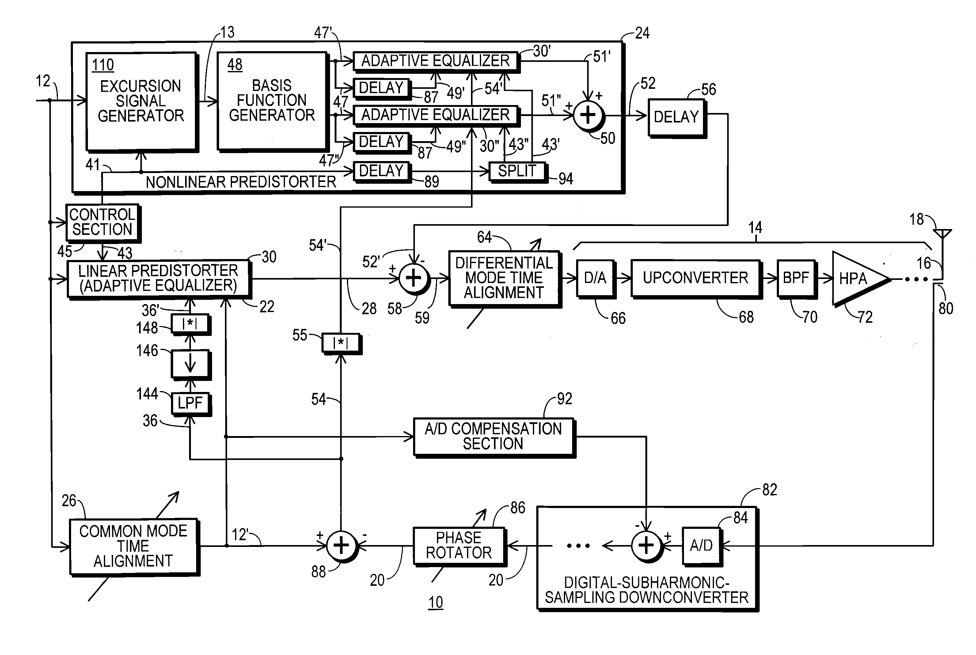
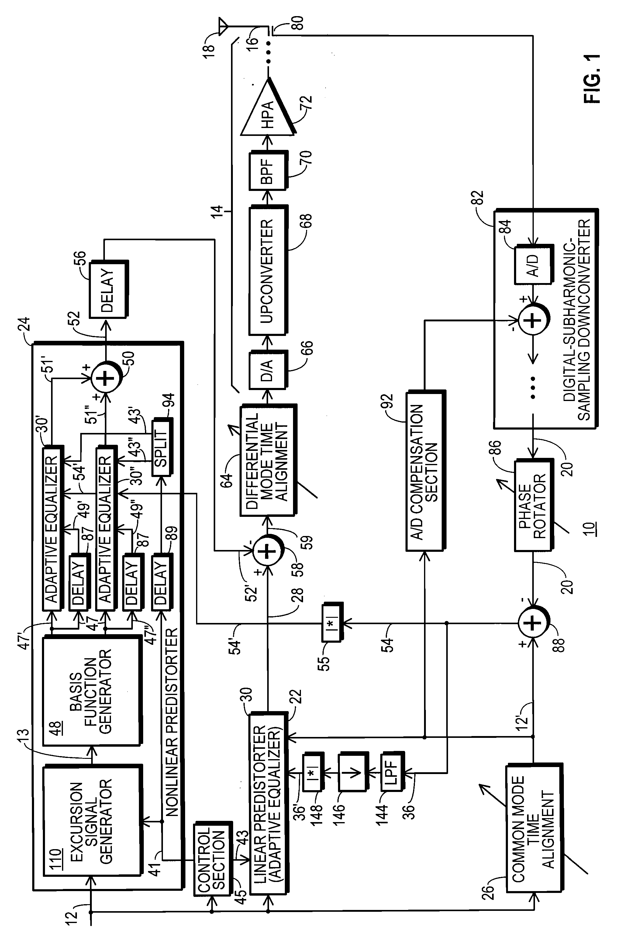
[0033]FIG. 1 shows a block diagram of an RF transmitter 10 configured in accordance with one embodiment of the present invention. RF transmitter 10 is adapted to receive a baseline communication signal 12. Baseline communication signal 12 is a complex digital signal having in-phase and quadrature components, preferably frequency-located at baseband.

[0034]As received at transmitter 10, baseline communication signal 12 has been digitally modulated to convey any and all data to be communicated by RF transmitter 10, using any of a wide variety of digital modulation techniques known to those skilled in the art. In addition, pulse-shape filtering may have been applied to reduce intersymbol interference in a manner known to those skilled in the art, signal peaks may have been limited to reduce a peak-to-average power ratio (PAPR), and other signal processing tasks may have been performed to produce baseline communication signal 12. Even though upstream tasks may have affected the magnitude...


PUM


Abstract

An RF transmitter (10) includes a nonlinear predistorter (24). The nonlinear predistorter (24) is implemented using adaptive equalizers (30′, 30″). A feedback signal (20) is developed by downconverting an RF communication signal (16). The feedback signal (20) is used in driving tap coefficients (34) for the adaptive equalizers (30′, 30″). The adaptive equalizers (30′, 30″) filter higher-ordered basis function signals (47′, 47″) generated from an excursion signal 13. The excursion signal 13 exhibits the same phase as a baseline communication signal (12) but has a magnitude that is reduced by a nonlinear threshold (100) when the baseline communication signal (12) exceeds the nonlinear threshold (100) and has a magnitude of zero at other times. The tap coefficients (34) may be formed from proto-coefficients (168) in response to the magnitude of the corresponding portion of the signal being filtered in the adaptive equalizers (30′, 30″).

Description

RELATED INVENTION[0001]This patent is related to “Transmitter Predistortion Circuit and Method Therefor,” by the inventors of this patent, Ser. No. 11 / 012,427, filed 14 Dec. 2004, which is a continuation-in-part of “Predistortion Circuit and Method for Compensating A / D and Other Distortion in a Digital RF Communications Transmitter,” by an inventor of this patent, Ser. No. 10 / 840,735, filed 6 May 2004, which is a continuation-in-part of “A Distortion-Managed Digital RF Communications Transmitter and Method Therefor” by an inventor of this patent, filed 27 Jan. 2004, Ser. No. 10 / 766,801, each of which is incorporated herein by reference.[0002]This patent is also related to “Equalized Signal Path with Predictive Subtraction Signal and Method Therefor” (Ser. No. 10 / 971,628, filed 22 Oct. 2004), “Predistortion Circuit and Method for Compensating Linear Distortion in a Digital RF Communications Transmitter” (Ser. No. 10 / 766,768, filed 27 Jan. 2004), and to “Predistortion Circuit and Meth...

Claims


Application Information

Patent Timeline
IPC IPC(8): H04L25/49
CPCH04L25/03044H04L25/03343H04L27/368
Inventor MCCALLISTER, RONALD DUANEBROMBAUGH, ERIC M.
Owner CRESTCOM INC
Learn More