High Efficiency 2-Stage Fuel Pump and Control Scheme for Gas Turbines

Active Publication Date: 2008-11-27
TRIUMPH ENGINE CONTROL SYST
View PDF10 Cites 31 Cited by
  • Summary
  • Abstract
  • Description
  • Claims
  • Application Information

AI Technical Summary

Benefits of technology

[0015]It is another object to provide a fuel pump system with a relatively small size and weight.
[0016]It is still

Problems solved by technology

This slewing is a transient event that can unacceptably starve the supply of fuel to the engine.
Under most operating conditions, this results in large amounts of pressurized fuel being returned to the pump inlet for recirculation.
The return and recirculation results in significant fuel heating due to additional energy being put into the fuel which is subsequently turned into heat as the pressure drops in the recirculation path.
In modern designs, fuel heating is a critical issue because the fuel is typically used as a heat exchanger to maintain proper operating temperature.
Other methods of heat exchange are undesirable because of the associated size, weight and cost.
Because a portion of the supply is subtracted to reset the pump, the resulting response is slow and creates flow disturbances to the engine.
Moreover, many prior art pump control systems lack the required stability to reliably provide fuel to the engine.
So despite the advances of t

Method used


Image

  • High Efficiency 2-Stage Fuel Pump and Control Scheme for Gas Turbines
  • High Efficiency 2-Stage Fuel Pump and Control Scheme for Gas Turbines
  • High Efficiency 2-Stage Fuel Pump and Control Scheme for Gas Turbines

Examples


Embodiment Construction

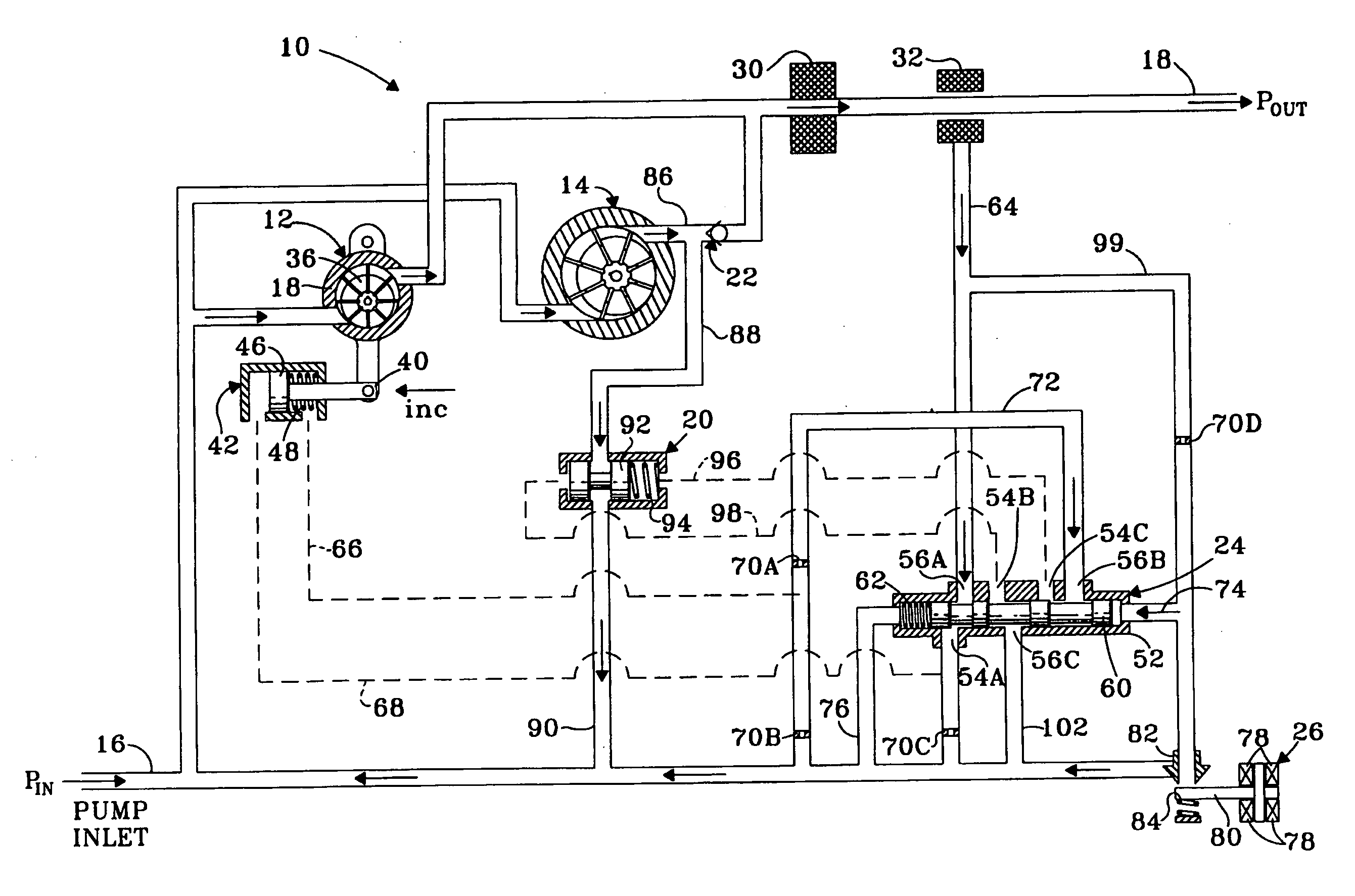
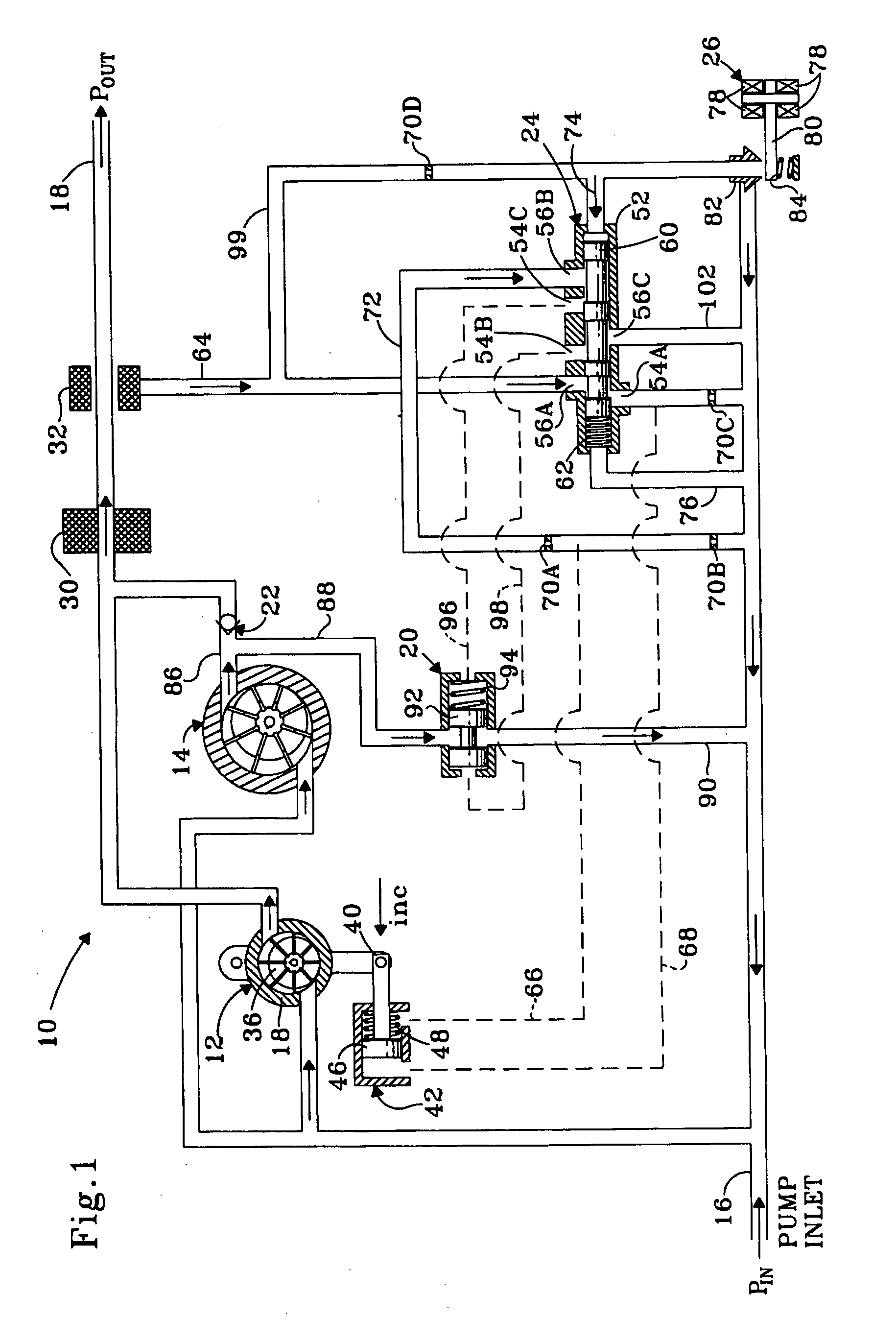
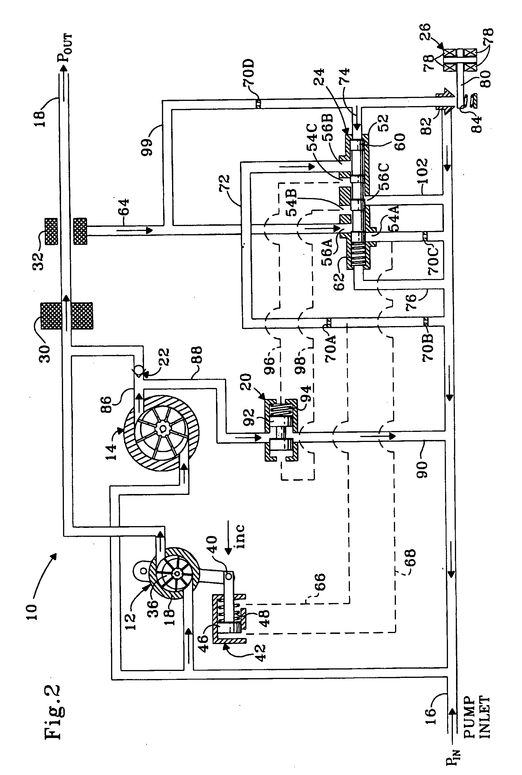
[0021]For clarity throughout the following description, arrows are shown within the lines of the FIGS. 1 and 2 to indicate the direction in which the fuel flows and an annotated letter “P” is shown to indicate pressure at certain locations. All relative descriptions herein such as left, right, up, and down are with reference to the Figures, and not meant in a limiting sense. Additionally, for clarity common items such as filters and shut off solenoids have not been included in the Figures as would be appreciated by those of ordinary skill in the pertinent art.

[0022]Referring now to FIG. 1, there is illustrated a schematic representation of a two-stage fuel pump system in accordance with the subject invention which is designated generally by reference numeral 10. In brief overview, the two-stage system 10 uses a variable first stage for steady-state operating conditions. During transient conditions that exceed the capacity of the first stage, a second fixed stage supplements the flow...


PUM

PropertyMeasurementUnit
Pressureaaaaaaaaaa
Flow rateaaaaaaaaaa
Areaaaaaaaaaaa

Abstract

A two-stage system for delivering fuel to a gas turbine including a first stage variable pump for serving as a primary source of fuel, a second stage fixed pump for selectively supplementing the variable pump, a bypass valve connected to the fixed pump for loading and unloading the fixed pump and a regulator valve assembly connected to the variable pump and the bypass valve for controlling operation of the variable pump and the bypass valve. Preferably, the two-stage system also includes a control valve connected to the regulator valve assembly for setting a pressure differential across the regulator valve assembly and, thereby, loading and unloading the fixed pump.

Description

CROSS-REFERENCE TO RELATED APPLICATION[0001]This application claims priority to U.S. Provisional Patent Application No. 60 / 629,585, filed Nov. 19, 2004, which is incorporated herein by reference.BACKGROUND OF THE INVENTION[0002]1. Field of the Invention[0003]The subject invention is directed generally to a system for delivering fluid flow, and more particularly, to a system for using two pumps to efficiently and quickly respond to high transient flow demands at a high pressure without excessive size or weight.[0004]2. Background of the Related Art[0005]In modern gas turbines, fuel pumps need to supply fuel to engine geometries. For example, in mid to larger class engines, linear pistons are used as guide vanes. The linear pistons require a significant source of fuel to slew. This slewing is a transient event that can unacceptably starve the supply of fuel to the engine. Thus, fixed delivery fuel pumps have often been sized to provide excessive fuel flow capacity in order to insure a...

Claims


Application Information

Patent Timeline
IPC IPC(8): F02C7/22F04B23/08
CPCF02C7/232F02C7/236F02C9/30F04C2/344F04C11/001F04C14/02F05D2260/85Y10T137/86171Y10T137/86019Y10T137/86139
Inventor DESAI, MIHIR C.
Owner TRIUMPH ENGINE CONTROL SYST
Why Eureka
Try Eureka