
Method and apparatus for controlling the combustion in a gas turbine

a gas turbine and combustion technology, applied in the direction of lighting and heating apparatus, turbine/propulsion fuel heating, machines/engines, etc., can solve the problems of interruption in the generation of energy, the operative cycle of the combustion system is reduced, etc., and achieve the effect of solving

Inactive Publication Date: 2008-11-27
NUOVO PIGNONE SPA
View PDF8 Cites 20 Cited by
  • Summary
  • Abstract
  • Description
  • Claims
  • Application Information

AI Technical Summary

Benefits of technology

[0009]One of the advantageous features of the disclosed subject matter is therefore to provide a method and apparatus for controlling the combustion of a gas turbine which is capable of effectively solving the drawbacks mentioned above.
[0010]In particular, another of the advantageous features of the disclosed subject matter is to provide a method and apparatus for controlling the combustion of a gas turbine which allows the use of gaseous fuels having significantly different Wobbe indexes, and therefore calorific values, and variable with time, without jeopardizing the performances of the turbine itself and maintaining the same geometry of the combustion chamber.
[0011]A further advantageous feature of the invention is to provide a method and apparatus for controlling the combustion of a gas turbine which allows the type of gaseous fuel fed to the turbine itself, to be rapidly varied.
[0012]Another advantageous feature of the invention is to provide a method and apparatus for controlling the combustion of a gas turbine which allows the turbine itself to function correctly also mixing two different gas fuels having a different Wobbe index, in arbitrary proportions and variable with time.
[0013]Yet another advantageous feature of the present invention is to provide a method and apparatus for controlling the combustion of a gas turbine which allows the turbine itself to deal with brusque variations (load sheds) in the power required by all the connections to the turbine.

Problems solved by technology

The use of different fuels, i.e. having high variations in the Wobbe index, in the same turbine can in fact lead to irregular combustion processes which can cause malfunctioning of the turbine itself, reduction in the operative cycle of the components of the combustion system and possible interruptions in the generation of energy.

Method used


Image

  • Method and apparatus for controlling the combustion in a gas turbine
  • Method and apparatus for controlling the combustion in a gas turbine
  • Method and apparatus for controlling the combustion in a gas turbine

Examples


Embodiment Construction

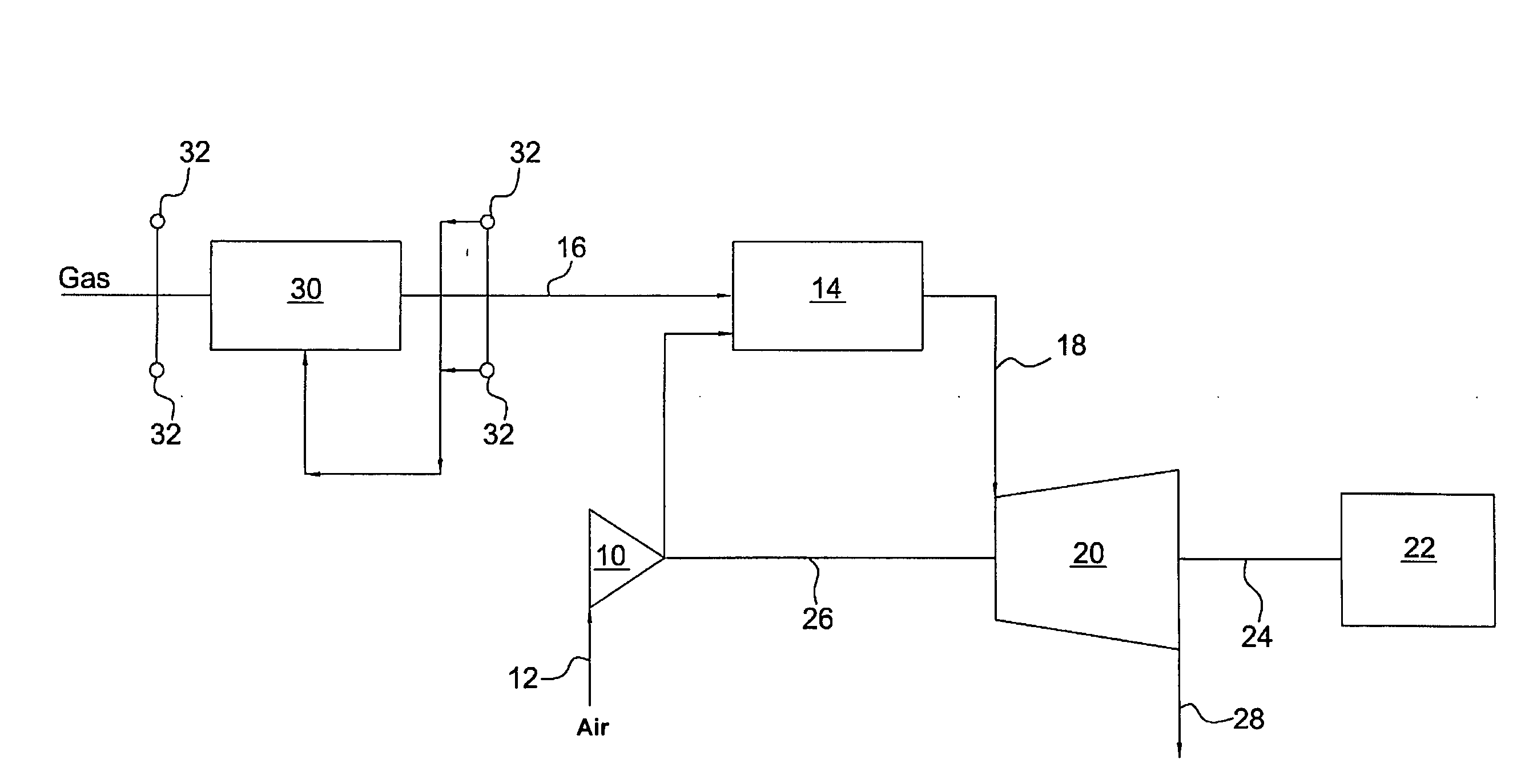
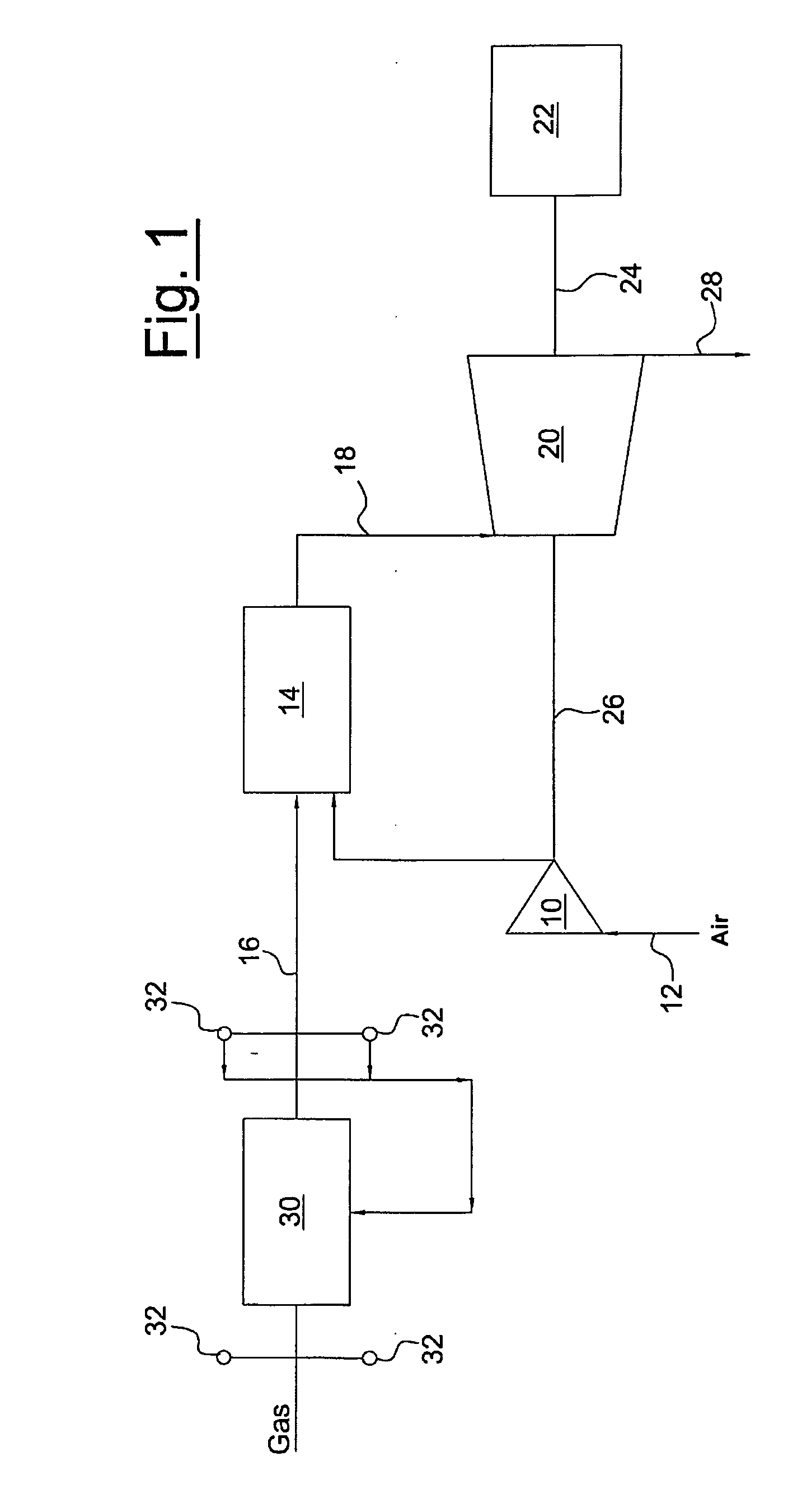
[0026]With reference in particular to FIG. 1, this schematically shows a generic gas turbine, comprising a compressor 10 capable of compressing air introduced therein through an inlet duct 12. The compressed air is then sent to a combustion chamber 14 to be mixed with the gaseous fuel coming from a supply duct 16. The combustion increases the temperature, the rate and volume of the gas flow and consequently the energy contained therein. Said gas flow is directed, through a duct 18, towards a turbine 20, which transforms the energy of the gas into work energy which can be exploited for activating operating machines, such as for example a generator 22 connected to the turbine 20 by means of a shaft 24. The turbine 20 also supplies the energy necessary for activating the compressor 10 through the relative shaft 26, whereas the discharge gases are expelled from the turbine 20 through an outlet duct 28.

[0027]According to the invention, there is at least one heat exchanger 30 on the suppl...


PUM


Abstract

A method and apparatus are described for controlling the combustion in a gas turbine. The method includes measuring, by means of one or two calorimeters, the temperature, calorific value and relative density of a gaseous fuel in order to determine the Wobbe index, comparing the Wobbe index value measured with a predefined Wobbe index value for the gaseous fuel and regulating the temperature of the gaseous fuel by means of at least one heat exchanger in order to reach the predefined Wobbe index value. The method may also include using a second gaseous fuel, having a different Wobbe index from the gaseous fuel, or a fuel obtained by mixing the gaseous fuel and the second gaseous fuel, according to arbitrary proportions and variable with time.

Description

BACKGROUND OF THE INVENTION[0001]1. Field of the Invention[0002]The present invention relates to a method and apparatus for controlling the combustion in a gas turbine and, more specifically, a method and apparatus for controlling the combustion in the presence of gaseous fuels having significantly different Wobbe indexes and variable with time.[0003]2. Description of the Related Art[0004]The use of gas turbines, normally consisting of a multiphase compressor, in which the air sucked from the outside is compressed, a combustion chamber, in which the combustion takes place of gaseous fuel added to the compressed air, and a turbine or expander, in which the gases coming from the combustion chamber are expanded, is known for the production of electric energy. The turbine is then capable of generating mechanical energy which can be exploited for activating operating machines or for feeding electric generators.[0005]There are various types of gases or gaseous mixtures which can be used a...

Claims


Application Information

Patent Timeline
Patent Type & Authority Applications(United States)
IPC IPC(8): F02C3/22F02C7/224F02C9/40
CPCF02C7/224F02C9/26F23K2401/10F23K2401/201F23K2900/01041F05D2270/303F23N1/002F23N2021/06F23N2021/10F23N2041/20F23K2900/05004F23N2221/06F23N2221/10F23N2241/20F23K2400/10F23K2400/201F02C9/28F02C7/00
Inventor ASTI, ANTONIOPACI, MARIATERESAD'ERCOLE, MICHELEBETTI, MASSLMOBEI, SIMONETONNO, GIOVANNISTEWART, JESSEORGERO, FRANCESCO MARIA
Owner NUOVO PIGNONE SPA
Learn More