Thin solid electrolytic capacitor having high resistance to thermal stress

a solid electrolytic capacitor and high resistance technology, applied in the direction of casings/cabinets/drawers, casings/cabinets/drawers details, electrical equipment, etc., can solve the problem of difficult to achieve the reduction of the thickness of the solid electrolytic capacitor, the difficulty of applying bending to the lead frame, and the difficulty of adapting to the recent thickness reduction. , to achieve the effect of relatively easy thickness reduction

Active Publication Date: 2008-11-27
TOKIN CORP
View PDF8 Cites 11 Cited by
  • Summary
  • Abstract
  • Description
  • Claims
  • Application Information

AI Technical Summary

Benefits of technology

[0007]On the other hand, in the case of a casing jointly using a substrate and a resin like in the CSP, the thickness reduction is relatively easy. However, since strong adhesion is required between the resin and the substrate, there is needed a resin having a strong adhesive force. Consequently, if this type of casing is used in a solid electrolytic capacitor, a capacitor element and the resin are also firmly bonded together. If, in this state, the solid electrolytic capacitor is subjected to thermal stress, for example, at the time of mounting on a board, there is a possibility that the resin expands to cause a problem that the surfaces of the capacitor element are subjected to stripping due to tensile stress caused by the expansion of the resin or the equivalent series resistance (hereinafter referred to as an “ESR”) increases.
[0008]It is therefore an exemplary object of this invention to provide a thin solid electrolytic capacitor with little possibility of causing such a problem even when subjected to thermal stress.

Problems solved by technology

However, as the reduction in thickness of the solid electrolytic capacitors advances, it becomes difficult to apply bending to lead frames thereof.
In view of this, the solid electrolytic capacitor disclosed in Japanese Unexamined Patent Application Publication (JP-A) No. 2000-77269 has difficulty in adapting to the recent thickness reduction.
Particularly, in the case of using the transfer mold method, the reduction in thickness of the solid electrolytic capacitors is difficult to achieve.
However, since strong adhesion is required between the resin and the substrate, there is needed a resin having a strong adhesive force.
If, in this state, the solid electrolytic capacitor is subjected to thermal stress, for example, at the time of mounting on a board, there is a possibility that the resin expands to cause a problem that the surfaces of the capacitor element are subjected to stripping due to tensile stress caused by the expansion of the resin or the equivalent series resistance (hereinafter referred to as an “ESR”) increases.

Method used


Image

  • Thin solid electrolytic capacitor having high resistance to thermal stress
  • Thin solid electrolytic capacitor having high resistance to thermal stress
  • Thin solid electrolytic capacitor having high resistance to thermal stress

Examples


first embodiment

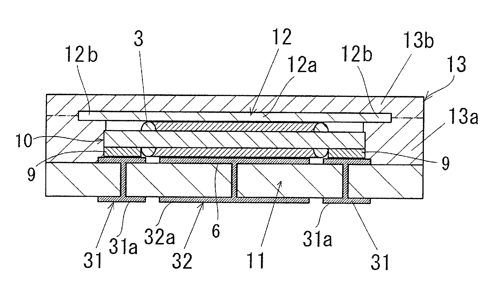
[0025]Referring to FIG. 2, a thin solid electrolytic capacitor according to this invention will be described.

[0026]The thin solid electrolytic capacitor of FIG. 2 includes a mounting substrate 11. A plurality of conductors 31 and 32 are attached to the substrate 11.

[0027]The capacitor element 10 is disposed on the substrate 11. The capacitor element 10 has an upper surface largely extending along the substrate 11 as compared with its height dimension from the substrate 11.

[0028]The thin solid electrolytic capacitor further includes a casing portion 13 at least part of which is made of a resin. The casing portion 13, jointly with the substrate 11, surrounds the capacitor element 10.

[0029]The casing portion 13 comprises a frame 13a disposed around the capacitor element 10 and bonded to the substrate 11, a cover 13b bonded to an upper surface of the frame 13a, and a plate-like non-adhesive member 12 disposed in tight contact with an inner surface of the cover 13b and fixed in the casin...

second embodiment

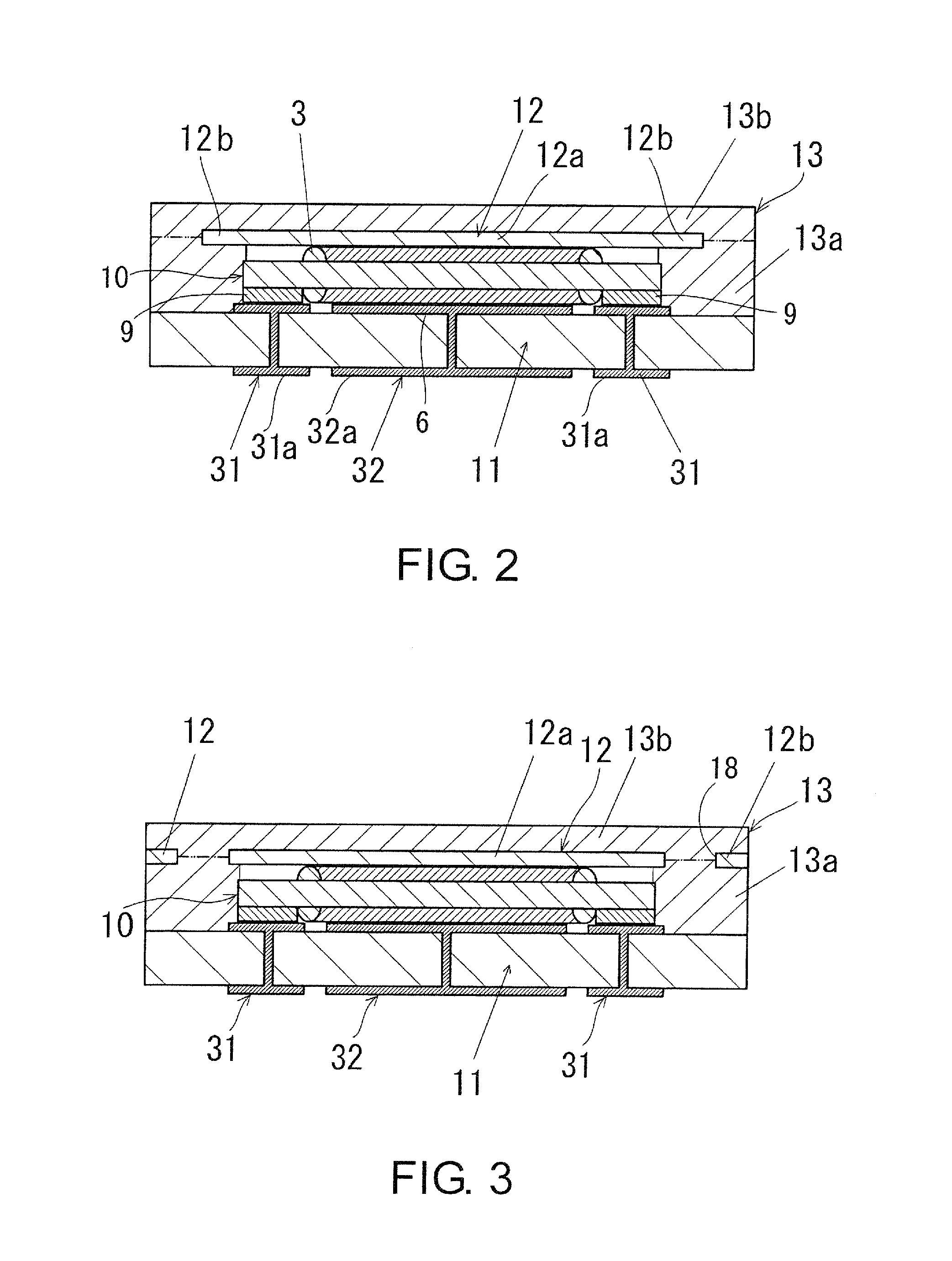
[0035]Referring to FIGS. 3 and 4A, a thin solid electrolytic capacitor according to this invention will be described. The same or corresponding portions are assigned the same reference symbols, thereby omitting description thereof.

[0036]In the thin solid electrolytic capacitor of FIG. 3, a plate-like non-adhesive member 12 has a number of openings 18 at its second portion 12b. Portions of a frame 13a and / or a cover 13b are inserted into these openings 18. Specifically, portions of a prepreg or an adhesive resin forming the frame 13a and / or the cover 13b enter the openings 18 of the non-adhesive member 12. Consequently, the non-adhesive member 12 is bonded to and substantially integrated with the frame 13a and the cover 13b.

[0037]According to the thin solid electrolytic capacitor of FIG. 3, positioning of the non-adhesive member 12 is easy and thus positional deviation thereof can be prevented, and therefore, it is possible to facilitate position matching of edges or corners of the ...

third embodiment

[0039]Referring to FIG. 5, a thin solid electrolytic capacitor according to this invention will be described. The same or corresponding portions are assigned the same reference symbols, thereby omitting description thereof.

[0040]In the thin solid electrolytic capacitor of FIG. 5, an adhesive 14 is coated on a substrate 11 around the capacitor element 10 bonded thereto under heat and pressure and a non-adhesive member 12 is bonded to the substrate 11 through the adhesive 14, thereby forming a casing portion 13. The fluidity of the adhesive 14 during heating is small.

[0041]Now, a description will be given of a specific method of manufacturing the thin solid electrolytic capacitor of FIG. 5.

[0042]A liquid epoxy resin was coated on the substrate 11 around the capacitor element 10 using a dispenser and, as the non-adhesive member 12, a plate member made of a liquid crystal polymer was placed on the liquid epoxy resin. The plate member was, in advance, surface-treated so as to be capable ...


PUM


Abstract

In a thin solid electrolytic capacitor including a solid electrolytic capacitor element disposed on a substrate, the solid electrolytic capacitor element has an upper surface largely extending along the substrate as compared with a height dimension thereof from the substrate. A casing portion is at least partly made of a resin and surrounds the solid electrolytic capacitor element jointly with the substrate. The casing portion includes a non-adhesive member that is in contact with an upper surface of the solid electrolytic capacitor element, but is not adhesive to the solid electrolytic capacitor element.

Description

[0001]This application is based upon and claims the benefit of priority from Japanese Patent Application JP 2007-134892, filed on May 22, 2007, the disclosure of which is incorporated herein in its entirety by reference.TECHNICAL FIELD[0002]This invention relates to a solid electrolytic capacitor that can be used for stabilizing the power supply voltage of an electronic device and reducing high-frequency noise thereof.BACKGROUND ART[0003]For example, Japanese Unexamined Patent Application Publication (JP-A) No. 2000-77269 discloses an example of a solid electrolytic capacitor. The solid electrolytic capacitor comprises a capacitor element using a valve-acting metal, a lead frame connected to the capacitor element, and a casing resin covering the capacitor element and a part of the lead frame. The lead frame is subjected to bending and then covered with the casing resin. The casing resin is applied to the capacitor element, for example, by a transfer mold method.[0004]There is also k...

Claims


Application Information

Patent Timeline
Patent Type & Authority Applications(United States)
IPC IPC(8): H01G9/08
CPCH01G9/08H01G9/15
Inventor TAKAHASHI, MASANORISAITO, TAKESHIKASUGA, TAKEOYOSHIDA, YUJIYOSHIDA, KATSUHIROSAKATA, KOJI
Owner TOKIN CORP
Why Eureka
Try Eureka