

Mini lightbar illuminators for LCE displays
- Summary
- Abstract
- Description
- Claims
- Application Information
AI Technical Summary
Benefits of technology
Problems solved by technology
Method used
Image

Examples
examples
[0076]One embodiment uses an acrylic light pipe as light channel 18, nominally ¼ in. square in cross section. The light pipe is highly transparent and has an optical finish on all sides and ends. To form light channel 18, a larger acrylic square bar (0.25″×0.25″×6 feet) was sawed into 14 inch segments and the ends were polished on a lathed. A piece of light extraction film was attached to one surface of light channel 18 with UV epoxy, dispensed using a syringe to form a uniform narrow epoxy bead down the length of light channel 18. The adhesive was then cured under a UV lamp.
[0077]An LED array is used as light source 16. Multi-die RGB LEDs are mounted in close proximity to light channel 18. These multi-die LEDS consist of 1 red, 1 blue and 2 green die in a single package (OSRAM OSTAR Projection devices, type LE ATB A2A, from OSRAM, Inc.) These devices can be individually turned on, with the brightness of each die controlled by a separate current source.
[0078]Another embodiment of an...
embodiments
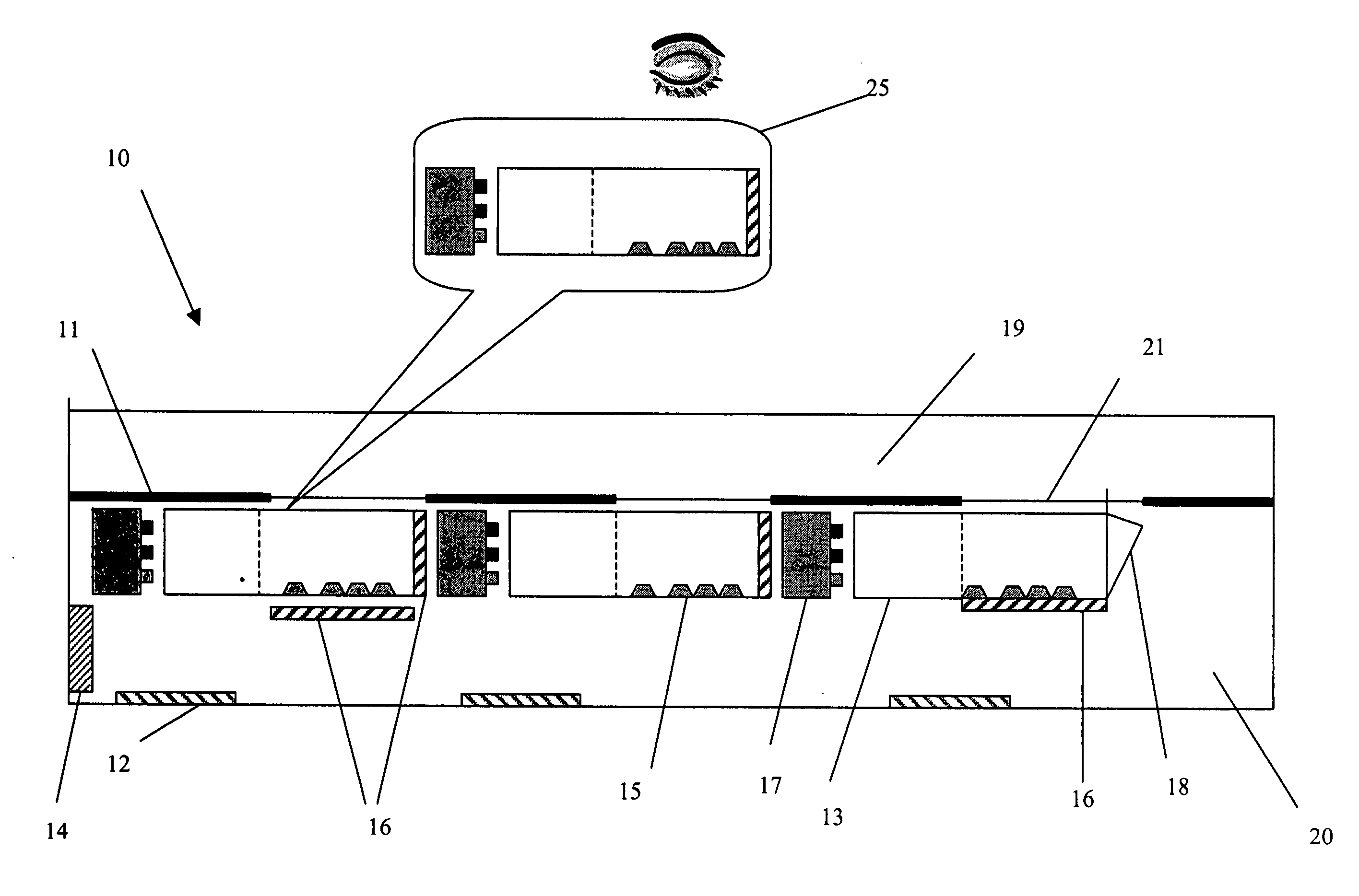
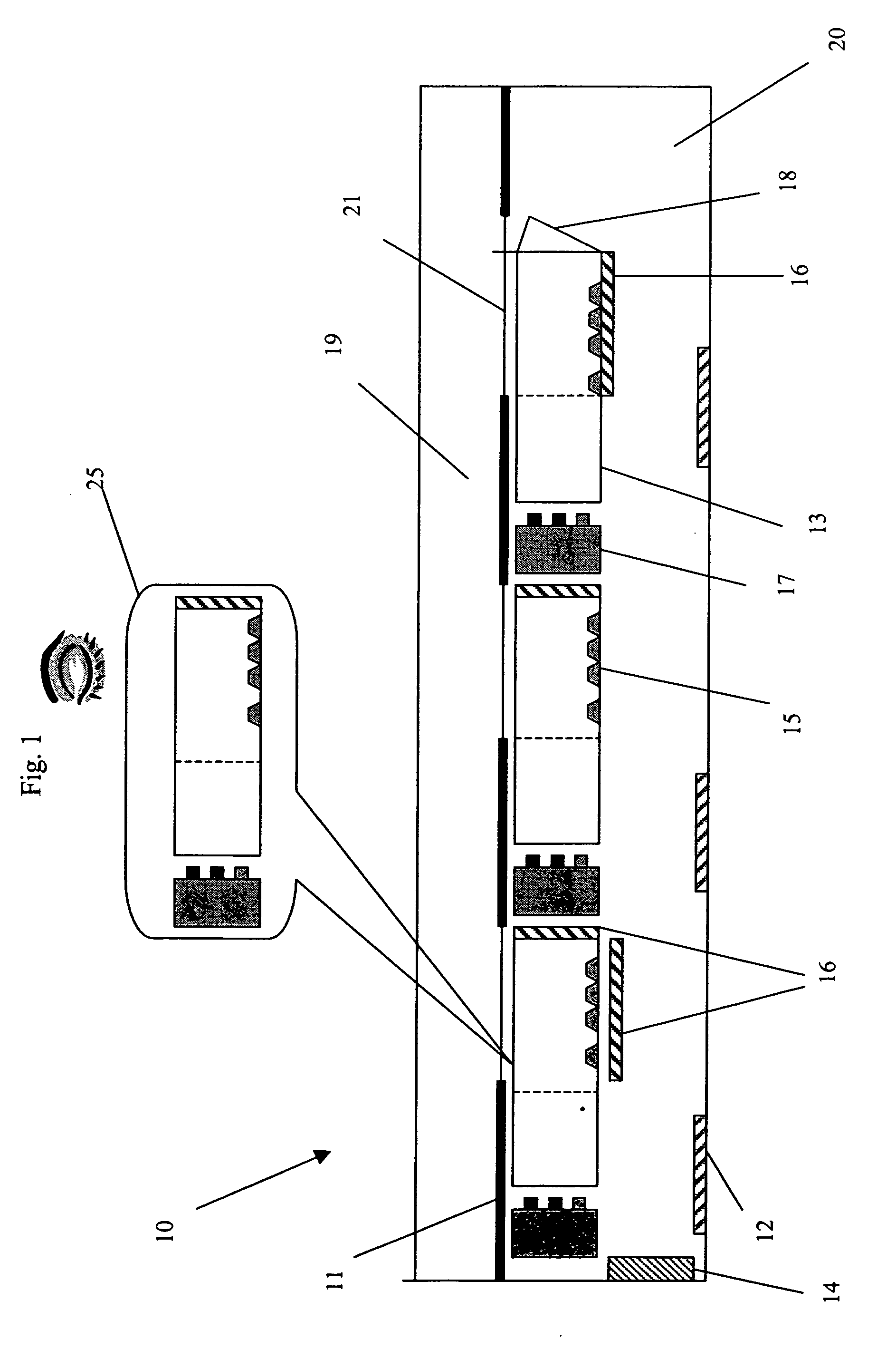
[0098]FIG. 1 is an improved backlight 10 for use in a display or light condition in which there are a series of mini-lightbars 25 below the reflector box 19. Reflector box 19 is an empty box with reflective surface. The reflective surface may be white with smooth or roughen surface for diffusive reflection or mirror-like specular reflection. The unique embodiment of this invention is that the light box contains nothing but light while there is a region below the reflector box that contains the light sources. Mini lightbars 25 comprise a solid state light source 17, a light bar with mixing section 13 and regions that contains light and a means of redirecting features 15 and a reflector 16 or 18. Reflector 16 and 18 may have an air gap between the light channel of the lightbar or it may be optically coupled to the mini lightbar. The reflector may be on at least 4 sides of the light channel. The sides include the bottom or non-view side, both sides and the end opposite of the light inp...
example
[0112]The color uniformity of a light pipe configured as light channel 18 according to the present invention was compared to the color uniformity of a light guide plate (LGP) for similar solid-state light sources. The light pipe was formed from PMMA and had a 6 mm square cross section and 245 mm length. A light extraction film was adhered to the topside of the light pipe. The light extraction film had prismatic features partly embedded into a layer of optical clear adhesive that forms regions of polymer next to regions of air. The adhesive (approximately 10 microns thick) was coated onto a sheet of polyester film. The polyester film was then adhered to the topside of the light pipe using an optically clear adhesive.
[0113]An array of LEDs was position on each end of the light pipe. The output light was measured as it exited the light extraction film. A point approximately midway between the LEDs and near the widthwise center of the light pipe (approximately 3 mm from an edge of the l...
PUM
 Abstract
Description
Claims
Application Information