Toner used for image forming apparatus

Active Publication Date: 2008-11-27
RICOH KK
View PDF16 Cites 29 Cited by
  • Summary
  • Abstract
  • Description
  • Claims
  • Application Information

AI Technical Summary

Benefits of technology

[0060]By setting the shape of a toner base particle within the defined range, an appropriate flowability of the toner can be maintained with time while keeping appropriate fixing properties and charge properties of the toner, and the toner hardly flocculates, and the transfer quality is not impaired.
[0061]In addition, by adding a plurality of types of fine particles to the surface of the toner base particle, toner properties in the early stage can be kept appropriate, and in the early stage, further stable transfer quality can be obtained.(Invention Aspect 3)
[0062]With this aspect, stability of developing property of the toner in a developing device can be improved, and further, uniformity of transfer of the toner layers at the time of transfer can be secured.(Invention Aspect 4)
[0063]When toner particles with smaller diameters are contained in a large amount, a BET-specific surface area of the toner is enlarged by just that match, therefore, appropriate toner properties, for example, not only transfer quality but also developing property or cleaning ability cannot be obtained because a coverage of the toner surface is lowered even when the same additives are used. As a result, the definition according to this aspect is necessary. With this aspect, appropriate toner properties can be secured and stable high image quality can be obtained in an early stage and even with time.(Invention Aspect 5)
[0064]By forming an image by means of an image forming apparatus using a toner according to any one of the invention aspects 1 to 4, stable high image quality can be obtained in an early stage and with time, and also when the toner degrades with time, marginal abilities as a system of the image forming apparatus can be improved such as in development, cleaning, and transfer.(Invention Aspect 6)
[0065]Even with the same degradation state of a toner, as the number of transfer times is increased during the time in which an image is fixed and output on a printing paper, the image quality becomes degraded. However, according to this aspect, reproducibility of thin lines can be secured even when transfer is repeated at a plurality of times.(Invention Aspect 7)

Problems solved by technology

However, a charging unit (1) using a corona discharge has drawbacks that a large quantity of ozone is produced, and NOx, etc., produced by the corona discharge, adhere to the image bearing member which causes problems with an image deletion with time.
Therefore it is difficult to reduce the cost of the image forming apparatus.
The contact type / proximate type charging units can solve above many drawbacks noted for a charging unit using corona discharge, however they cause such a problem that a wear amount of the image bearing member increases, which shortens the lifetime of the image bearing member.
Furthermore, occurrence of noise is also a drawback when an alternating current is used for voltage applied.
In addition, since a charging unit (1) rubs against an image bearing member with a toner or paper powder, the surface of the image bearing member is further contaminated and a drawback due to contamination of charging unit surface occurs.
However, this method causes nonuniform particle diameters and nonuniform particle shapes of the toners and they are difficult to be controlled.
When an image is formed using a toner with a widely dispersed distribution of particle diameter, it substantially causes drawbacks that a fine powder toner contaminates a developing sleeve, contact / proximate charging unit, cleaning blade, photoconductor, and carrier, and causes toner scattering, which make it difficult to satisfy both high image quality and high reliability.
However, when a toner with reduced particle diameters and similar particle diameters is used, problems with cleaning ability arise.
In particular, in blade cleaning it is impossible to remove a toner having similar and reduced particle diameters stably.
Note, however, that when a toner is deformed to too much degree minute dot reproducibility degrades with unstable behaviors of the toner in developing step.
Use of an aqueous granulation toner makes it difficult to maintain cleaning ability level.
However, this technology could not prevent the image bearing member from wear due to discharge and due to a contact with members, because areas on the image bearing member where no toner was supplied (a non-image area) were not coated with the lubricant.
However, this technology could not prevent the image bearing member from wear due to discharge and to contact with members, because areas on the image bearing member where an untransferred residual toner was present (image area), were not coated with the lubricant.
At this time, when an electrostatic or nonelectrostatic adhesion force to the object on which the toner image was formed before the transfer is high, the whole of the toner layer can not be transferred at the central part of the thin line where the toner layer strongly flocculates, which results in a transfer defect (missing the central part of thin line).
Furthermore, this phenomenon tends to take place in a situation when developer is stirred for long time in an environment of few replacements of a toner in a development container and the toner degrades with time.
As a result flowability of the toner become poor.
And above described poor transfer (missing the central part of thin line) is considered to tend to take place in above situations because of an increase in nonelectrostatic adhesion force of the toner and easy flocculation of the toner layer.

Method used


Image

  • Toner used for image forming apparatus
  • Toner used for image forming apparatus
  • Toner used for image forming apparatus

Examples


example 1

[0178]Into a reaction tank equipped with a condenser tube, a stirrer, and a nitrogen inlet tube, 229 parts of bisphenol A ethyleneoxide (dimolar) adduct, 529 parts of bisphenol A propionoxide (trimolar) adduct, 208 parts of terephthalic acid, 46 parts of adipic acid, and 2 parts of dibutyl tin oxide were poured, and were reacted under a normal pressure at 230° C. for 8 hours. Then the mixture was reacted under a reduced pressure of 10 mmHg to 15 mmHg for 5 hours, 44 parts of trimellitic acid anhydride were added into the reaction tank, and an unmodified polyester resin was synthesized by subjecting the reactant to a reaction under a normal pressure at 180° C. for 2 hours.

[0179]The thus obtained unmodified polyester resin had a number average molecular weight of 2,500, a weight average molecular weight of 6,700, a glass transition temperature of 43° C., and an acid number of 25 mg KOH / g.

[0180]Using a HENSCHEL MIXER (manufactured by Mitsuikozan Co., Ltd.), 1,200 parts of water, 540 pa...

example 2

[0215]A toner was produced in the same manner as in Example 1 except that the addition amount of the modified laminar inorganic mineral (trade name: CLAYTONE APA) was changed from 3 parts to 0.1 parts.

[0216]Physical properties of the toner thus obtained (example B) are shown in Table 1.

example 3

[0217]A toner was produced in the same manner as in Example 1 except that a laminar inorganic mineral montmorillonite at least in part modified with an ammonium salt having a polyoxyethylene group (CLAYTONE HY manufactured by Southern Clay Products, inc.) was used instead of CLAYTONE APA.

[0218]Physical properties of the toner thus obtained (example C) are shown in Table 1.


PUM

PropertyMeasurementUnit
Lengthaaaaaaaaaa
Diameteraaaaaaaaaa
Fractionaaaaaaaaaa

Abstract

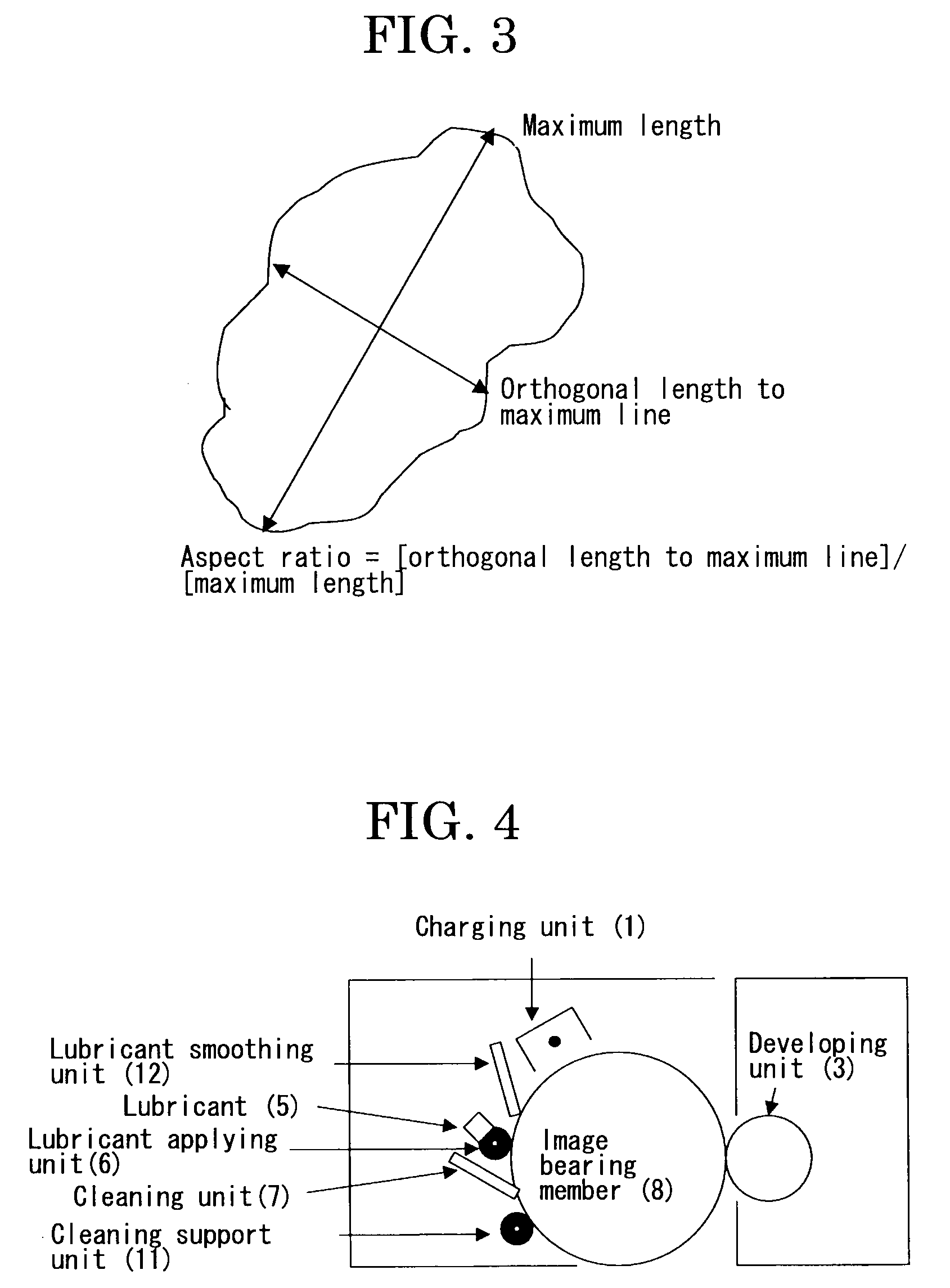
The present invention provides an image forming apparatus capable of stably producing high quality images with time, without causing missing a central part of a thin line, however, with keeping an appropriate flowability of a toner. The toner used in the image forming apparatus is a toner which contains a binder resin, a colorant, and a laminar inorganic mineral in which at least part of an ion in layers is modified with an organic ion, the toner is granulated in an aqueous system, the volume average particle diameter Dv of the toner is in the range of 3.0 μm<Dv<6.5 μm, the aspect ratio of the toner is 0.81 to 0.89, and the surface of the toner is externally added with a plurality of types of fine particles.

Description

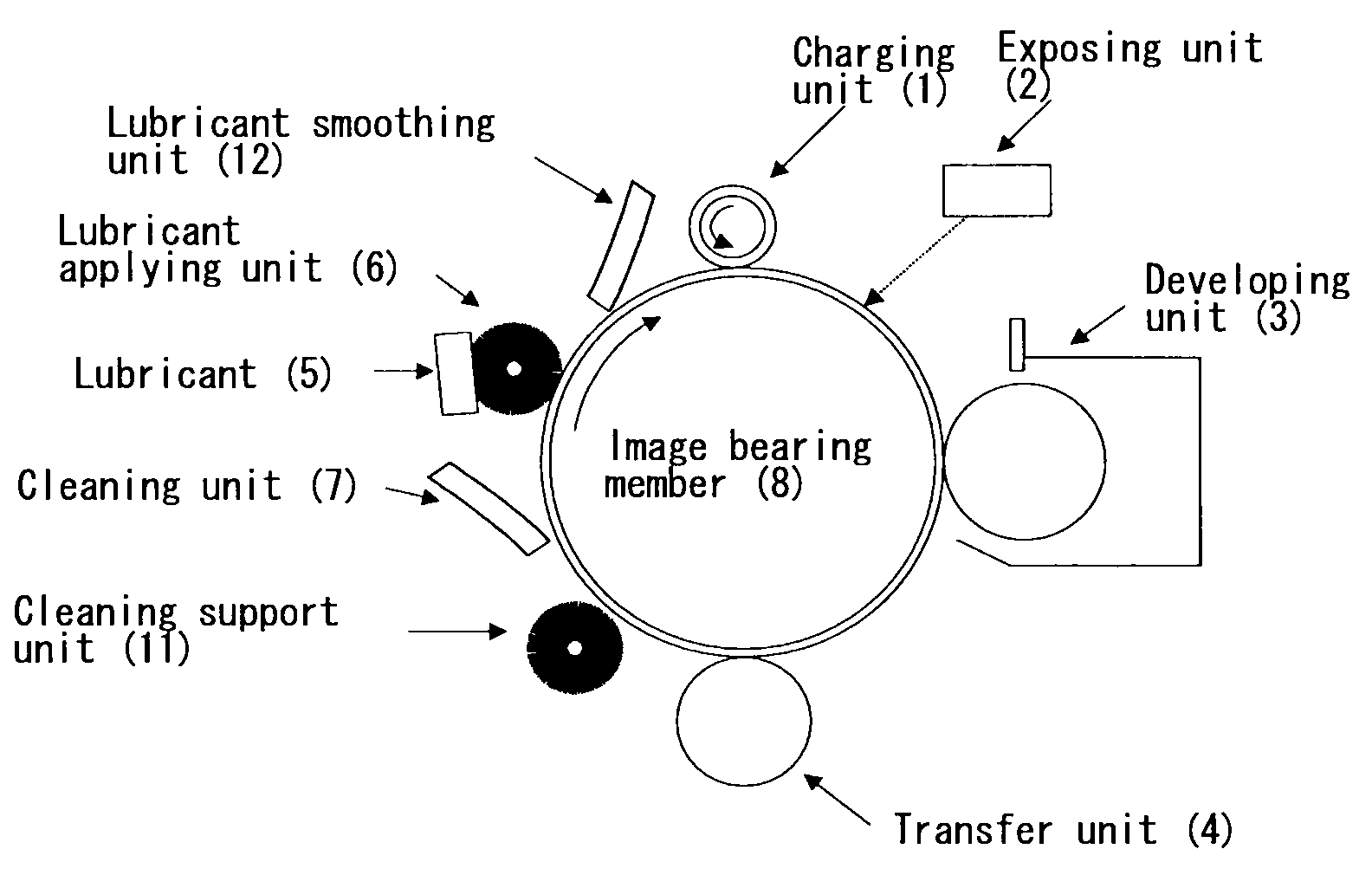
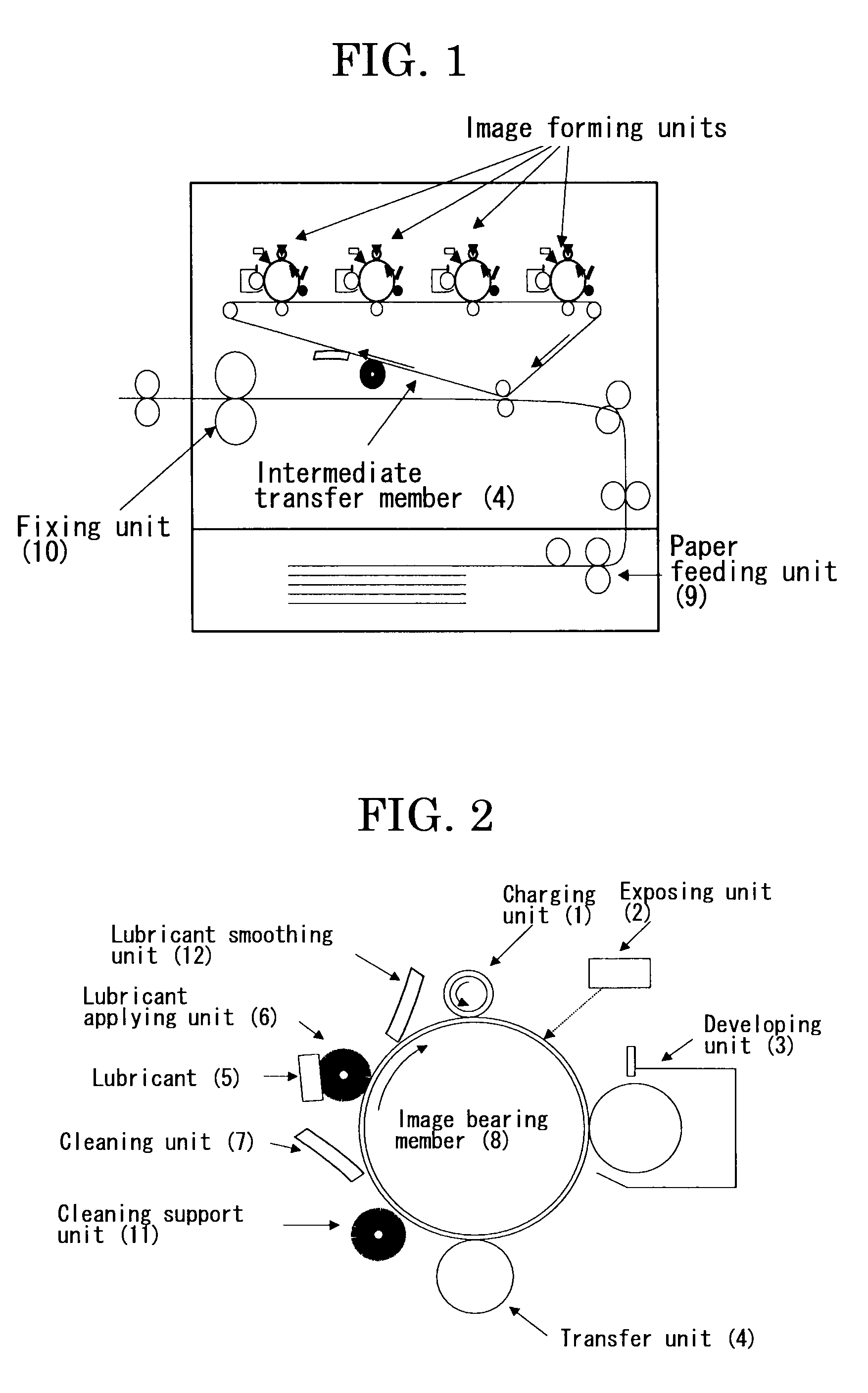
BACKGROUND OF THE INVENTION[0001]1. Field of the Invention[0002]The present invention relates to an image forming apparatus, such as copiers and printers, and specifically relates to a toner used in an image forming apparatus having at least an image bearing member, a charging unit, a developing unit, a transfer unit, a cleaning unit, a lubricant applying unit containing a lubricant.[0003]2. Description of the Related Art[0004]FIGS. 1 and 2 are respectively an illustration showing the entire configuration of a conventional image forming apparatus.[0005]The image forming apparatus forms an image by charging uniformly an image forming area on an image bearing member by means of a charging unit, by writing the image on the image bearing member by means of an exposing unit, and using a toner frictionally charged on the image bearing member by means of a developing unit. Then, the image on the image bearing member is transferred onto a printing paper by means of a transfer unit directly ...

Claims


Application Information

Patent Timeline
IPC IPC(8): G03G15/08
CPCG03G9/0819G03G9/0827G03G9/08755G03G9/08795G03G9/08797G03G9/09708G03G9/09716
Inventor SESHITA, TAKUYAAWAMURA, JUNICHISUZUKI, TOMOMISAWADA, TOYOSHIYAMADA, MASAHIDE
Owner RICOH KK
Why Eureka
Try Eureka