
Wireless Communication Mimo System With Repeaters

Inactive Publication Date: 2008-11-27
TELEFON AB LM ERICSSON (PUBL)
View PDF8 Cites 40 Cited by
  • Summary
  • Abstract
  • Description
  • Claims
  • Application Information

AI Technical Summary

Benefits of technology

[0009]The objective problem that is solved by the present invention is to provide an arrangement suitable for a MIMO system, which arrangement is capable of providing sufficient communication between a base station having at least two spatially separated antennas and a user equipment also having at least two spatially separated antennas, when a number of obstacles are situated in the signal path, deteriorating the SNR. Furthermore, the solution should provide an arrangement which improves the SNR for the MIMO communication streams, also leading to a larger coverage area for the use of MIMO.

Problems solved by technology

However, in an urban environment, where a user equipment (for example a mobile phone or a portable computer) is arranged for communicating with such a base station, a number of objects such as large buildings may block the signal path between the base station and the user equipment, causing a number of reflections.
Therefore, the signal to noise ratio (SNR) becomes deteriorated, and thus the signals transmitted between the base station and the user equipment become more and more noisy the more buildings that are in the way.
This solution presents a problem, since, if the frequency domain is used, there is a shortage of frequencies to be used due to spectral shortage.
If the time domain is used, the system becomes slow.

Method used


Image

  • Wireless Communication Mimo System With Repeaters
  • Wireless Communication Mimo System With Repeaters
  • Wireless Communication Mimo System With Repeaters

Examples


Embodiment Construction

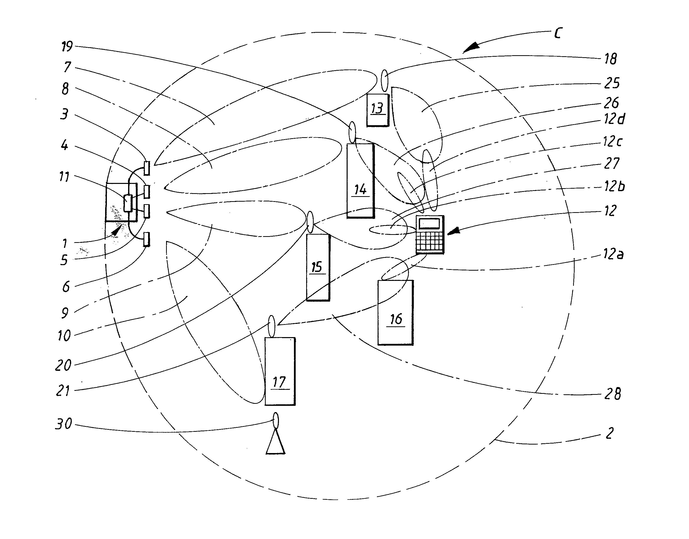
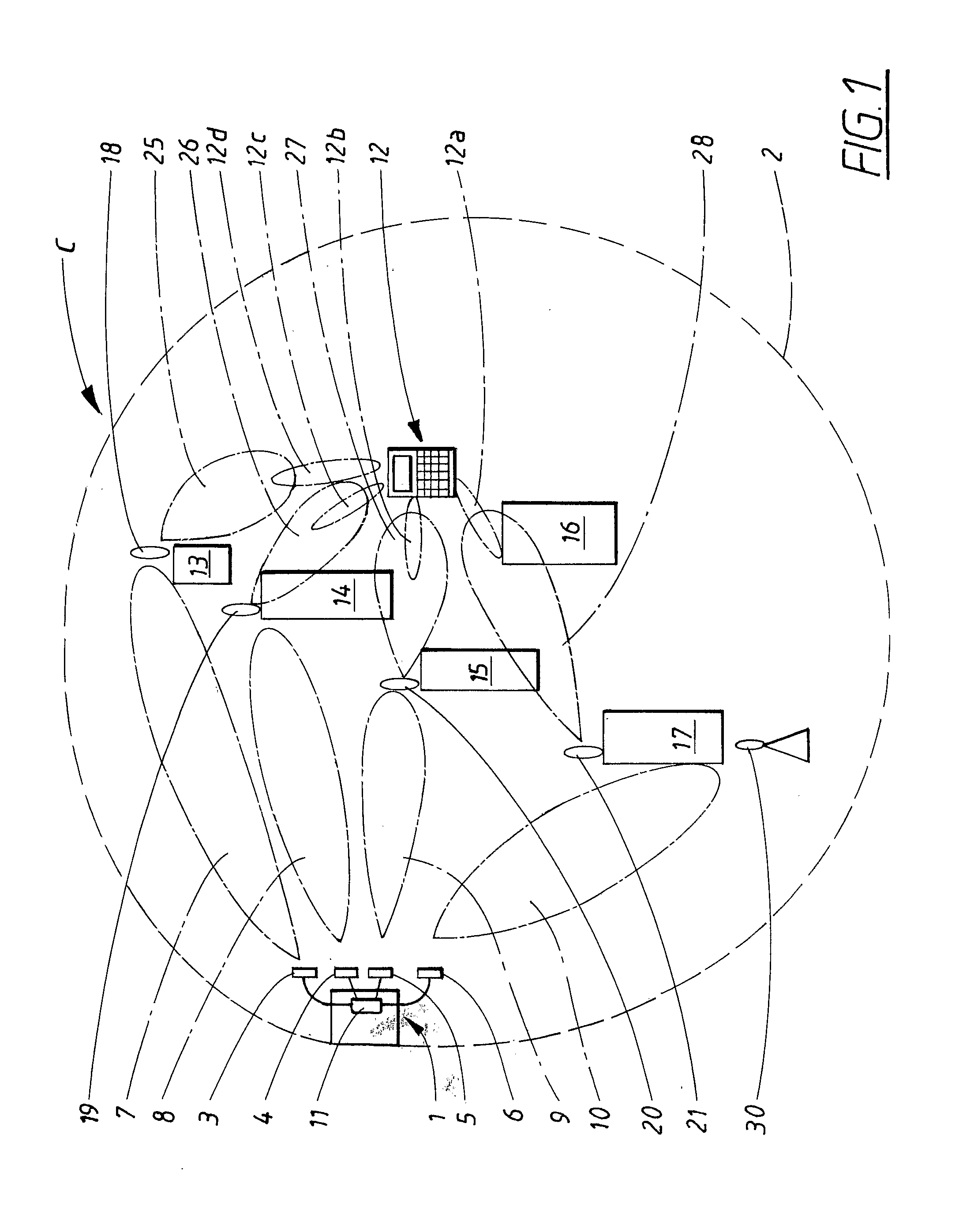
[0021]FIG. 1 shows a wireless communication system (C) comprising a base station 1 arranged for communication in a MIMO (Multiple Input Multiple Output) system is placed in such a way that it covers a communication cell 2. According to a first embodiment example, the base station 1 is equipped with a first 3, second 4, third 5 and fourth 6 antenna, which antennas are spatially separated by approximately 0.5-1 wavelengths (calculated from the centre frequency of the frequency band for which the antennas are designed). In this example, each antenna 3, 4, 5, 6 is arranged for a single polarization. The four antennas 3, 4, 5, 6 produce first 7, second 8, third 9 and fourth 10 antenna radiation lobes.

[0022]These antennas 3, 4, 5, 6 receive and transmit signals, using the same frequency band for the uplink and another frequency band for the downlink. The spatial separation is, in a previously known manner, adapted in such a way that the communicated signals in the respective antenna lobes...


PUM


Abstract

The present invention relates to a wireless communication system (C) comprising at least one base station (1) in a communication cell (2), from which base station (1) at least two essentially uncorrelated antenna radiation lobes (7, 8, 9, 10) are formed. Each antenna radiation lobe (7, 8, 9, 10) communicates a MIMO (Multiple Input Multiple Output) communication stream. The system (C) further comprises at least one repeating transmitter / receiver (repeater) (18, 19, 20, 21), which is arranged for communicating one of the MIMO communication streams to and / or from at least one UE (user equipment) (12). The present invention also relates to a repeater that is a part of the system (C), and a method for communicating at least two MIMO communication streams to and / or from at least one UE (user equipment) (12), using at least one repeater (18, 19, 20, 21).

Description

TECHNICAL FIELD[0001]The present invention relates to a wireless communication system comprising at least one base station in a communication cell, from which base station at least two essentially uncorrelated antenna radiation lobes are formed, each antenna radiation lobe communicating a MIMO (Multiple Input Multiple Output) communication stream.[0002]The present invention also relates to repeating transmitter / receiver (repeater).[0003]The present invention also relates to a method for communicating at least two MIMO communication streams to and from at least one UE (user equipment), comprising the step: communicating the MIMO communication streams by means of at least two at least two essentially uncorrelated antenna radiation lobes.BACKGROUND ART[0004]The demand for wireless communication systems has grown steadily, and is still growing, and a number of technological advancement steps have been taken during this growth. In order to acquire increased system capacity and user bit r...

Claims


Application Information

Patent Timeline
IPC IPC(8): H04B7/04
CPCH04B7/022H04B7/026H04B7/1555H04B7/2606
Inventor ANDERSSON, MATS HGORANSSON, BO
Owner TELEFON AB LM ERICSSON (PUBL)
Learn More