
Apparatus and Method for Guided Chronic Total Occlusion Penetration

a technology guided penetration, which is applied in the field of guided penetration of chronic total occlusion, can solve the problems of reducing the diameter of the lumen, affecting the treatment effect, and affecting the patient's recovery, so as to facilitate the treatment of the occlusion, facilitate the accurate placement of the guide wire, and facilitate the penetration of the cto

Inactive Publication Date: 2008-11-27
MEDINOL LTD
View PDF13 Cites 154 Cited by
  • Summary
  • Abstract
  • Description
  • Claims
  • Application Information

AI Technical Summary

Benefits of technology

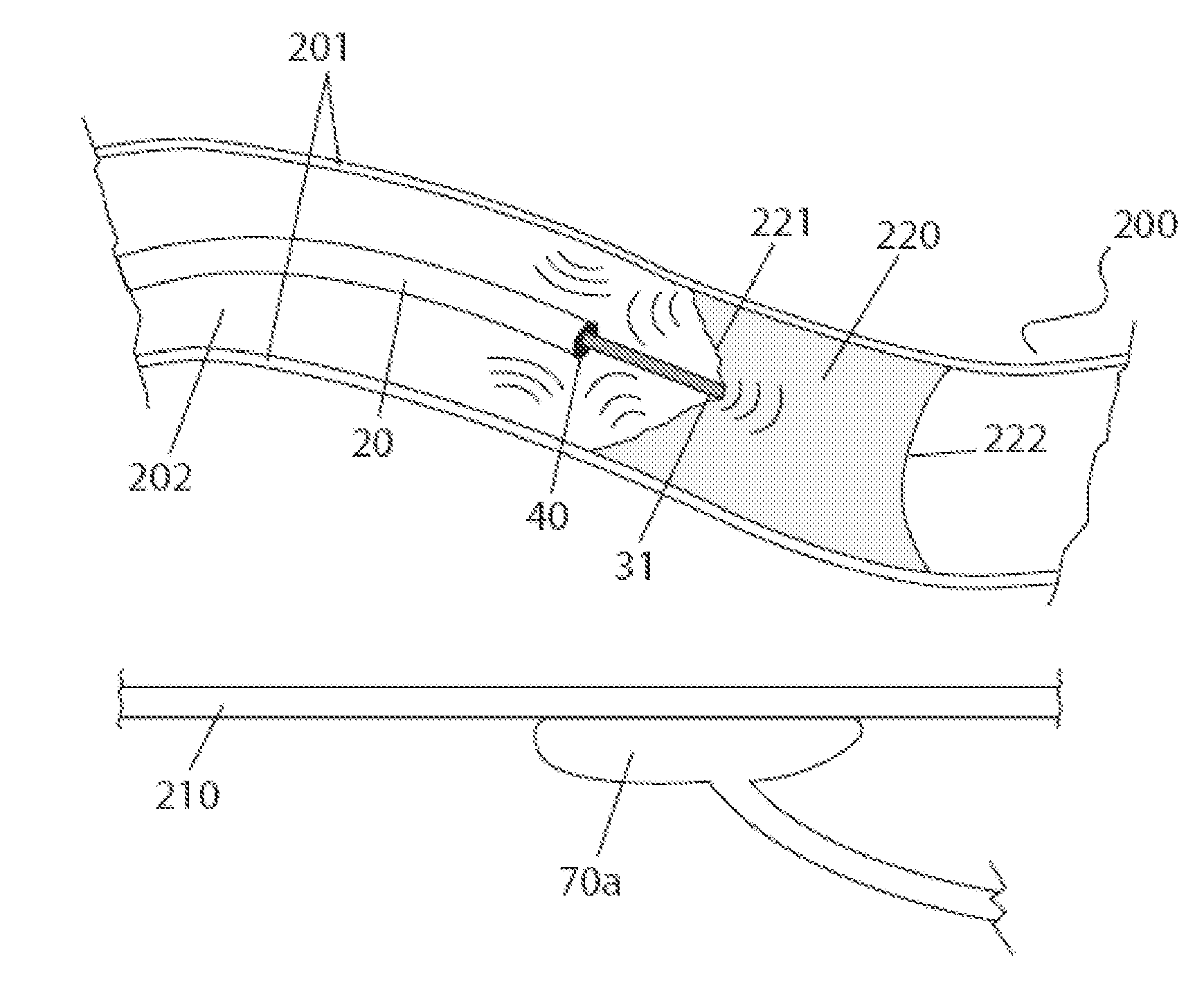
[0010]The invention is laid down in the attached claims, wherein advantageous embodiments thereof are subject-matter of the dependent claims, respectively. The present invention generally relates to an apparatus that facilitates accurate placement of guide wire and drilling tip within the blood vessel during recanalization of a CTO or lesion and a method of using such an apparatus. The apparatus comprises a detection system that permits differential processing of ultrasonic frequency signals from the guide wire, occlusion and vessel walls using one or more signal receivers that can be oriented at different angles with respect to the area being treated. Preferably, the detection system is an imaging system, more preferably the imaging system is capable of generating real-time three-dimensional images of the CTO or lesion, the blood vessel and the distal tip of the guide wire. Preferably, the apparatus also facilitates penetration of a CTO or other obstructions in a vessel. The method of using the apparatus of the invention facilitates treatment of the occlusion and avoids or reduces the complications and risks associated with treating an occlusion, such as perforation of the walls of the vessel and creation of a false lumen.
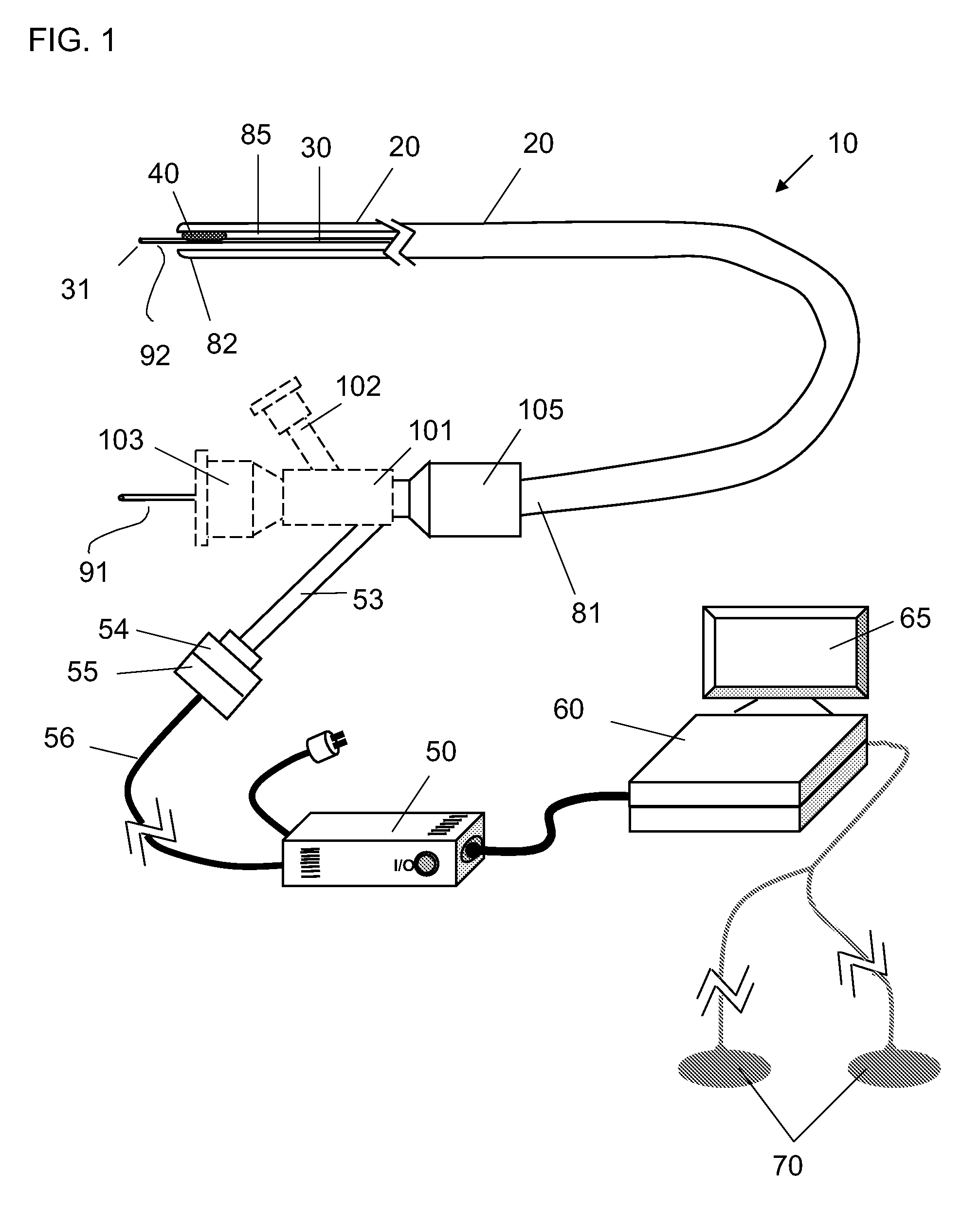
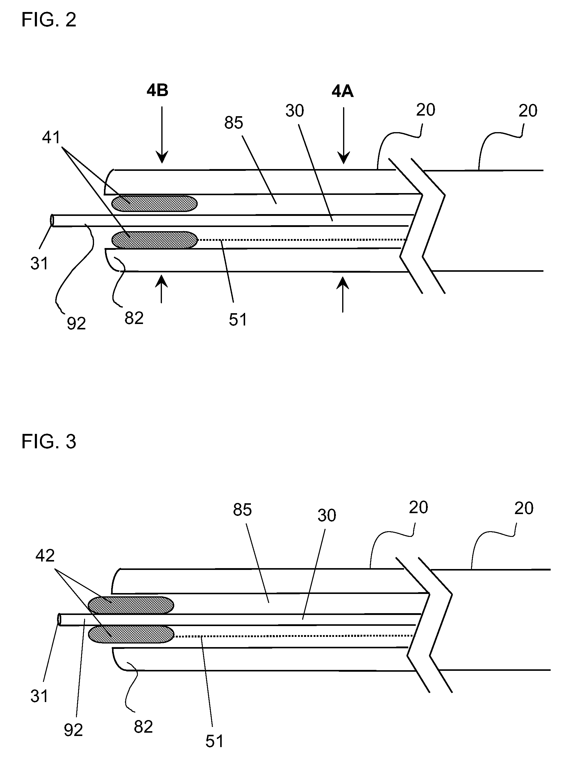
[0012]One embodiment relates to a system comprising a drilling component for use in penetrating an occlusion in a body lumen coupled to an imaging component that permits visualization of the drilling procedure resulting in lower risk and fewer complications. The power source and controller work together to energize the transducer causing the therapeutic tip to vibrate or oscillate at a desired frequency. The controller permits operation of the transducer over a range of frequencies and amplitudes, including at frequencies and amplitudes that are useful in drilling and frequencies and amplitudes that are detectable by the receivers. The controller, power source, transducer, therapeutic tip and catheter work together to generate detectable signals from the body lumen and, with the one or more receivers and an imaging system, generate real-time images of the distal end of the guide wire and catheter relative to the walls of the body lumen and the occlusion. This permits the operator to visualize the therapeutic tip and to guide the therapeutic tip and guide wire through the occlusion and away from the vessel walls.
[0013]A preselected range of vibrational frequencies generated by the energy-generating system facilitates recanalization of an occluded vessel by energizing an oscillating ceramic motor to a vibrational frequency and amplitude, in particular a vibrational frequency and amplitude sufficient for the therapeutic tip to operate as a drilling device, e.g., to penetrate the occlusion. The oscillating ceramic motor is also made to vibrate at a frequency detectable by the imaging system. In a preferred embodiment, the energy generating system energizes the oscillating ceramic motor to vibrate at an ultrasonic frequency.

Problems solved by technology

This buildup leads to a gradual reduction in the diameter of the lumen over time and the subsequent restriction of blood flow.
Until recently, the most common method of treating CTO was bypass surgery, which is a procedure that, unfortunately, involves considerable risk and trauma to the patient.
While CTO containing soft plaques are often amenable to penetration with a guide wire, CTO containing hard plaques are often difficult to penetrate successfully with a guide wire, especially where the lesion is heavily calcified.
Such situations introduce additional and highly undesirable complexity to the procedure, requiring removal of the guide wire and reinsertion of a stiffer wire.
Further, when the tip of the guide wire encounters and fails to penetrate the CTO, it can veer towards the wall of the vessel, thereby possibly damaging, or worse, perforating the vessel wall and other times forming a false lumen.
These methods have the disadvantage of only providing a two-dimensional image and of not being able to precisely determine the position of the catheter's distal end relative to the occlusion.
While these patents describe a method of penetrating the CTO, they do not disclose a way to accurately direct the placement of the catheter during the procedure.

Method used


Image

  • Apparatus and Method for Guided Chronic Total Occlusion Penetration
  • Apparatus and Method for Guided Chronic Total Occlusion Penetration
  • Apparatus and Method for Guided Chronic Total Occlusion Penetration

Examples


Embodiment Construction

[0020]The present invention generally provides a system for use in guiding an apparatus through a body lumen—such as intravascularly—with accuracy, so as to avoid or reduce the risk of perforating the lumen wall or creating a false lumen. The system comprises a flexible, elongated catheter having a proximal and distal end with at least one lumen extending longitudinally therethrough; a guide wire, also having a proximal and distal end and further having a tip, e.g., a therapeutic tip, at its distal end; a transducer capable of being energized to vibrate at a detectable frequency, which in turn causes the therapeutic tip to vibrate; a power source; a controller for controlling the power source; and a detection system. The detection system comprises one or more receivers and utilizes the controller, which further comprises a processor, for converting signals detected by the receivers into differentiable information. Preferably, the detection system is an ultrasound-based imaging syste...


PUM


Abstract

An apparatus and method for guided penetration of a chronic total occlusion in a blood vessel are disclosed. The invention is directed to an apparatus that facilitates accurate placement of a drilling tip within a body lumen using ultrasound-based detection to determine the position of the intravascular catheter relative to the vessel occlusion and vessel walls.

Description

[0001]This application claims benefit of priority under 35 U.S.C. §120 to U.S. Provisional Application Ser. No. 60 / 939,766 filed May 23, 2007, entitled “Apparatus and method for ultrasound imaging guided chronic total occlusion penetration.”FIELD OF THE INVENTION[0002]The invention relates generally to an apparatus and method for the guided penetration of a chronic total occlusion (CTO) in a blood vessel and, more particularly, to the use of an ultrasound-based detection system to direct catheter and drill placement during penetration of an occlusion.BACKGROUND[0003]One of the leading causes of human mortality is cardiovascular disease. This commonly begins with stenotic lesions of the coronary arteries, which occur, for example, as a result of the gradual buildup of atheromata, or plaques, along the vessel walls. This buildup leads to a gradual reduction in the diameter of the lumen over time and the subsequent restriction of blood flow. A chronic total occlusion results when a blo...

Claims


Application Information

Patent Timeline
Patent Type & Authority Applications(United States)
IPC IPC(8): A61B5/05A61B17/22
CPCA61B8/0833A61B8/0841A61B8/12A61B8/445A61B17/2202A61B2017/22038A61B2019/5285A61B8/483A61B2090/3788
Inventor RICHTER, JACOB
Owner MEDINOL LTD
Learn More