
Control data modification within a cache memory

a data modification and cache memory technology, applied in memory architecture accessing/allocation, computer security arrangements, sustainable buildings, etc., can solve the problems of data having to be copied from main memory, consuming power, and affecting the effect of cache load and cache flushing speed

Active Publication Date: 2008-11-27
ARM LTD
View PDF6 Cites 26 Cited by
  • Summary
  • Abstract
  • Description
  • Claims
  • Application Information

AI Technical Summary

Benefits of technology

[0009]The present techniques recognise that in at least some circumstances it is possible to avoid cache flushing and cache reloading operations, i.e. maintaining the cache data as valid, by modifying control data associated with that cached data within the cache memory rather than flushing the data and then reloading the data with its new control data. As an example, if a large block of data values is being processed by a particular program thread and the cache memory includes control data which permits access by that particular program thread but not other program threads and it is desired to provide access to that data to another program thread, then the standard technique would be to flush the data from the cache and then reload that data with the new control data appropriate to provide access to the new program thread. However, the present technique recognises that program instructions executed by the processor may be used to directly modify the control data within the cache memory so as to permit access by the new program thread and thereby avoid flushing and reloading with its associated speed and power consumption penalties.
[0011]Another example of control data which may be modified arises in a system in which the processors have a plurality of access states (e.g. security modes) associated therewith and only certain of these states permit access to controlled regions of memory. The control data within the cache memory can specify the access states which must be current for a processor in order for it to be able to access the cache data concerned. In this context, it may be desired to restrict access to a given access state of a processor for one period of time and then to open up the access to a different access state, possibly with a different processor, at a later time. The present technique permits program instructions executing on at least one of the processors to modify the access control data to permit such changes at the level of the cache memory without requiring cache flushing and cache reloading. Such an arrangement may, for example, be conveniently used within a system having multiple processors with the access data specifying the identity (e.g. number) of the processor or processors permitted to access particular portions of the cache data. This control data can be dynamically modified without having to flush and reload the cache data, i.e. maintaining the validity of the data over such a modification.
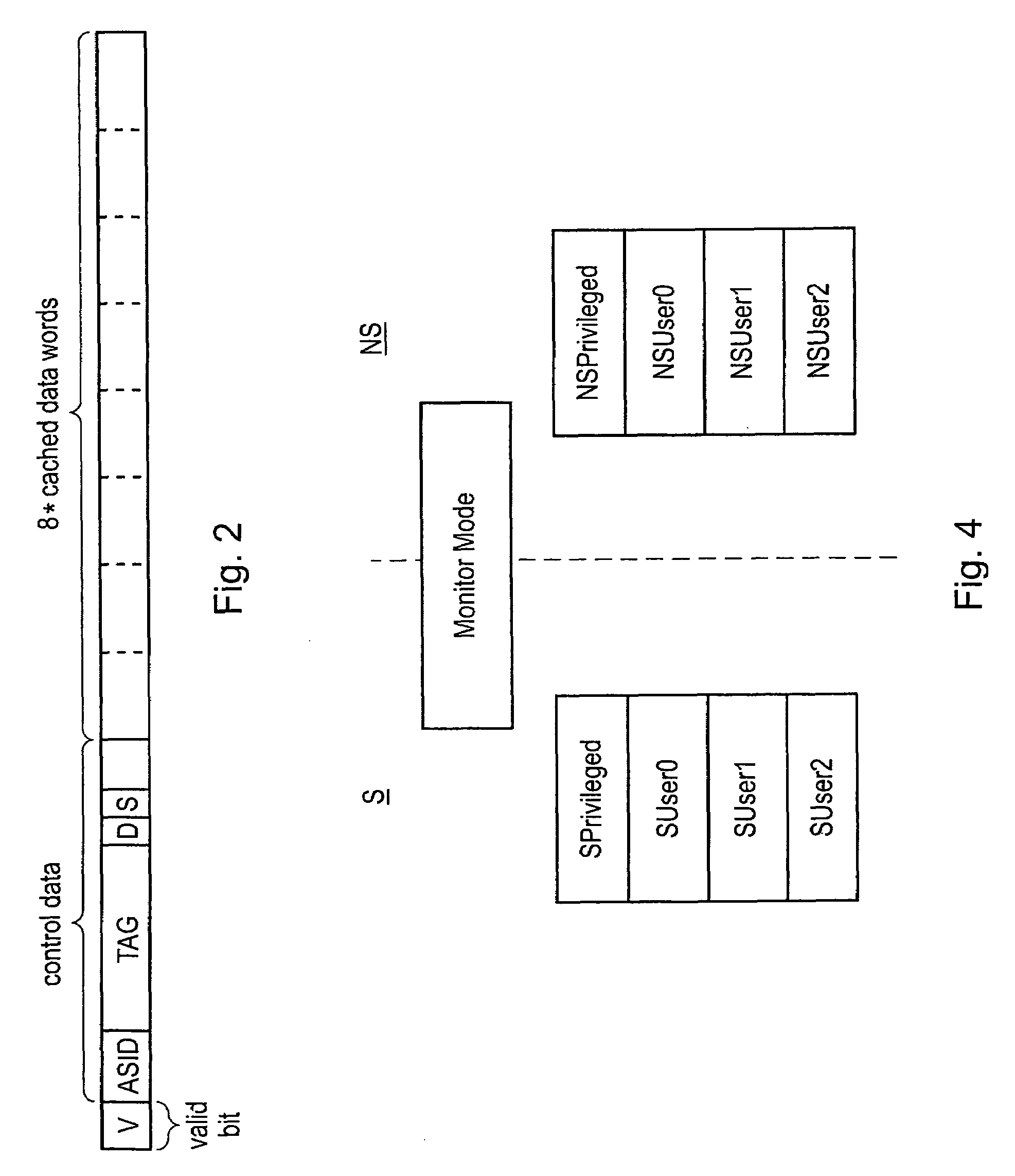
[0012]The present technique is particularly useful when at least one of the processors has a secure state and a non-secure state with the control data being used to restrict access to cache data cached from secure regions of memory to only processors operating in the secure state. In accordance with the present technique, a processor executing in the secure state may be permitted to execute program instructions changing the control data specifying that only processors in the secure state may access certain cache data thereby opening up access to that data to processors executing in a non-secure state. This type of behaviour is particularly useful in fields such as digital rights management where large volumes of data may need to be manipulated both in a secure state and a non-secure state with the present technique providing a way of reducing the amount of cache flushing and cache reloading which might otherwise be required.
[0014]The present technique may be used with good advantage within systems employing memory protection units which are programmable by at least one of the processors so as to specify which regions of the memory are secure and which regions are non-secure. The processor in such a system is already devolved control over security and accordingly can be trusted to make appropriate modifications to the control data within the cache memory in accordance with the present technique.
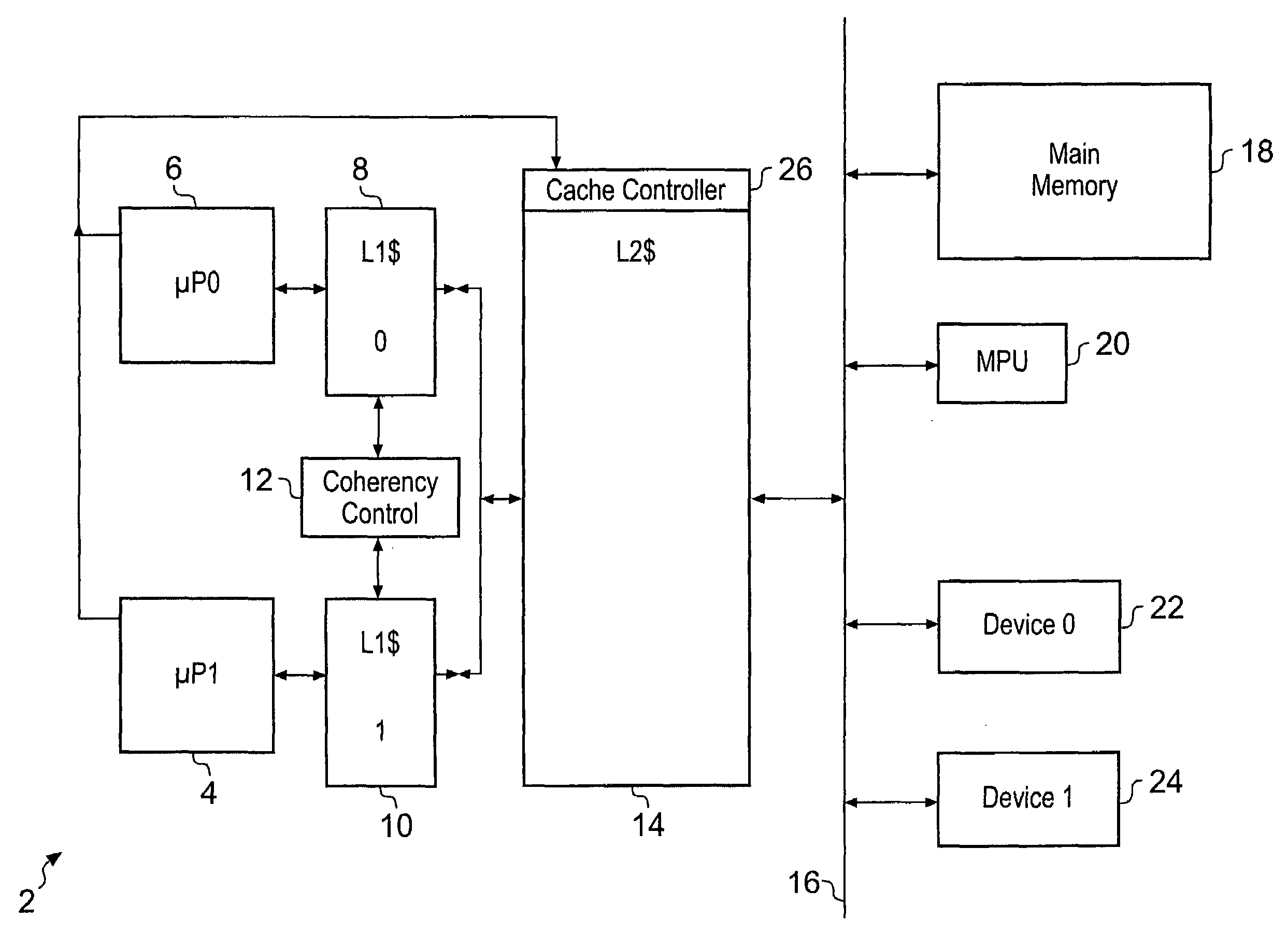
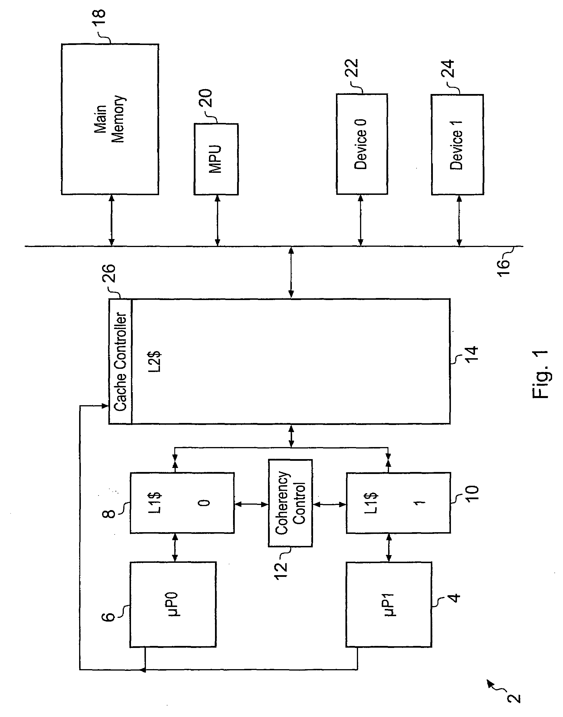
[0015]It will be appreciated by those in this technical field that there is often provided a hierarchy of cache memories within a data processing system. This is particularly the case within systems including more than one processors. It is common for a processor to have a small level-1 cache memory and access to a larger level-2 cache memory. Whilst the present technique can be employed in relation to either or both of these memories, the control complexity associated with applying the technique for multiple levels of cache memory within a cache memory hierarchy is high, e.g. to avoid race conditions between modifications to control data being performed for coherency at the various levels within the hierarchy. Accordingly, it is practical to restrict use of the present technique to one level within the cache hierarchy. In this context, a larger benefit is achieved by applying the present technique at the level-2 cache memory since this is typically larger and accordingly avoiding the need to flush and reload larger volumes of data associated with the level-2 cache memory is more advantageous compared to the smaller volumes of data typically associated with level-1 cache memories.
[0017]It may also be advantageous to avoid potential aliasing problems within the cache memory when a change in control data is made by adapting the cache memory to respond to program instructions for changing the control data to additionally identify cache lines which will alias with the new cache data with its modified control data and flush those aliasing cache lines from the cache memory.

Problems solved by technology

Whilst cache memories improve processing speed, they have the disadvantage of consuming power in that data has to be copied from main memory to the cache memory, from where it can be further manipulated, rather than being directly taken from the main memory.
Cache loads and cache flushes in this way are also relatively slow.
A particular problem arises in circumstances, such as context switches, when large amounts of data must be flushed from a cache memory and then new data loaded into the cache memory.
This is disadvantageously slow and consumes a disadvantageous amount of power.

Method used


Image

  • Control data modification within a cache memory
  • Control data modification within a cache memory
  • Control data modification within a cache memory

Examples


Embodiment Construction

[0035]FIG. 1 schematically illustrates a data processing system 2 including multiple processors 4, 6 each having a level-1 cache memory 8, 10. Coherency control circuitry 12 is responsible for maintaining coherency between the two level-1 cache memories 8, 10 and accordingly, if a change is made to the control data associated with the cache line in one of the level-1 cache memories 8, 10, then the coherency control circuitry 12 identifies this change and then makes the corresponding change within the other of the level-1 cache memories 8, 10.

[0036]A relatively large level-2 cache memory 14 is shared between the processors 4, 6 and is coupled to a main system bus 16. Also coupled to the main system bus are a main memory 18, which includes different regions having different access permissions associated therewith (e.g. secure regions, non-secure regions etc). A memory protection unit 20 is responsible for policing access to the main memory 18 by either of the processors 4, 6 or either...


PUM


Abstract

A data processing system is provided with at least one processor 4, 6, a main memory 18 and a cache memory 14. Cache data within the cache memory 14 has validity data V and control data associated therewith. The control data controls access to the cached data. Program instructions executed by the processors 4, 6 control a cache controller 26 to modify the control data associated with the cached data whilst it remains stored within the cache memory 14 and remains valid. The control data may, for example, specify a security flags indicating whether access is restricted to secure processes or processors.

Description

BACKGROUND OF THE INVENTION[0001]1. Field of the Invention[0002]This invention relates to the field of data processing systems. More particularly, this invention relates to the control of cache memories within data processing systems.[0003]2. Description of the Prior Art[0004]It is known to provide data processing systems with cache memories so as to increase the processing speed by making access to data and / or instructions faster. Whilst cache memories improve processing speed, they have the disadvantage of consuming power in that data has to be copied from main memory to the cache memory, from where it can be further manipulated, rather than being directly taken from the main memory. Furthermore, when the data is no longer required in the cache memory, then it must be written back to the main memory if it has been changed so as to maintain consistency. Cache loads and cache flushes in this way are also relatively slow. A particular problem arises in circumstances, such as context ...

Claims


Application Information

Patent Timeline
Patent Type & Authority Applications(United States)
IPC IPC(8): G06F12/08G06F12/0837G06F12/084G06F12/128
CPCG06F12/084Y02B60/1225G06F2212/1052G06F12/1425G06F12/1491G06F21/00G06F21/6218G06F2212/1028Y02D10/00G06F12/0837G06F12/128
Inventor HARRIS, PETER WILLIAMFELTON, DONALD
Owner ARM LTD
Learn More