Thermal type flow meter and engine control system using the same

a flow meter and flow control technology, applied in the field of thermodynamics, can solve the problems of high production cost, increased pressure loss, contamination on the surface, etc., and achieve the effects of reducing size, facilitating installation space assurance, and reducing pressure loss and production cos

Inactive Publication Date: 2008-12-04
HITACHI LTD
View PDF9 Cites 34 Cited by
  • Summary
  • Abstract
  • Description
  • Claims
  • Application Information

AI Technical Summary

Benefits of technology

[0018]The flow meter measuring apparatus constructed as above has an advantage that a sensor can be reduced in size to facilitate assurance of installation space and to decrease the pressure loss and the production cost as well.

Problems solved by technology

This type of thermal flow meter faces a problem that because of the independently separate arrangement of heating resistor and temperature measuring resistor in the fluid, the installation space increases, the pressure loss increases and the production cost is high.
But the temperature measuring resistor being at a relatively low temperature cannot evaporate the oil component deposited on its surface and as a result, contaminants cumulate on its surface.
With the contaminants cumulated, the fluid temperature cannot possibly be detected accurately and errors in measurement of flow rate will take place.
As is clear from equation (1), the liquid flow rate is inverse proportional to the square of a difference in temperature between the two heating resistors and therefore, if the temperature difference between the two heating resistors is small, errors are liable to develop in the flow rate obtained from equation (1).
Therefore, in order to utilize the technique described in the above Patent Document, there needs another heating resistor for which temperature setting is discriminatively different from that for the plural heating resistors, raising a problem that the sensor structure becomes complicated.
Further, the technique described in the aforementioned JP-A-59-136620 fails to consider heat dissipation or transfer from the heating resistor to its support member, resulting in a problem that if the heating resistor is at high temperatures and heat dissipation to its support member cannot be negligible vis-à-vis heat dissipation to the liquid, the error in flow rate detection grows.
The latter technique, however, faces a problem that if the fluid temperature and the flow rate change at higher periods than the period of turn on and off of the switch, accuracy in flow rate detection will be degraded.
As known in the art, high-frequency pulsations take place in the course of intake and exhaust of an engine and the error in measurement will possibly grow in the pulsation field as above.

Method used


Image

  • Thermal type flow meter and engine control system using the same
  • Thermal type flow meter and engine control system using the same
  • Thermal type flow meter and engine control system using the same

Examples


Embodiment Construction

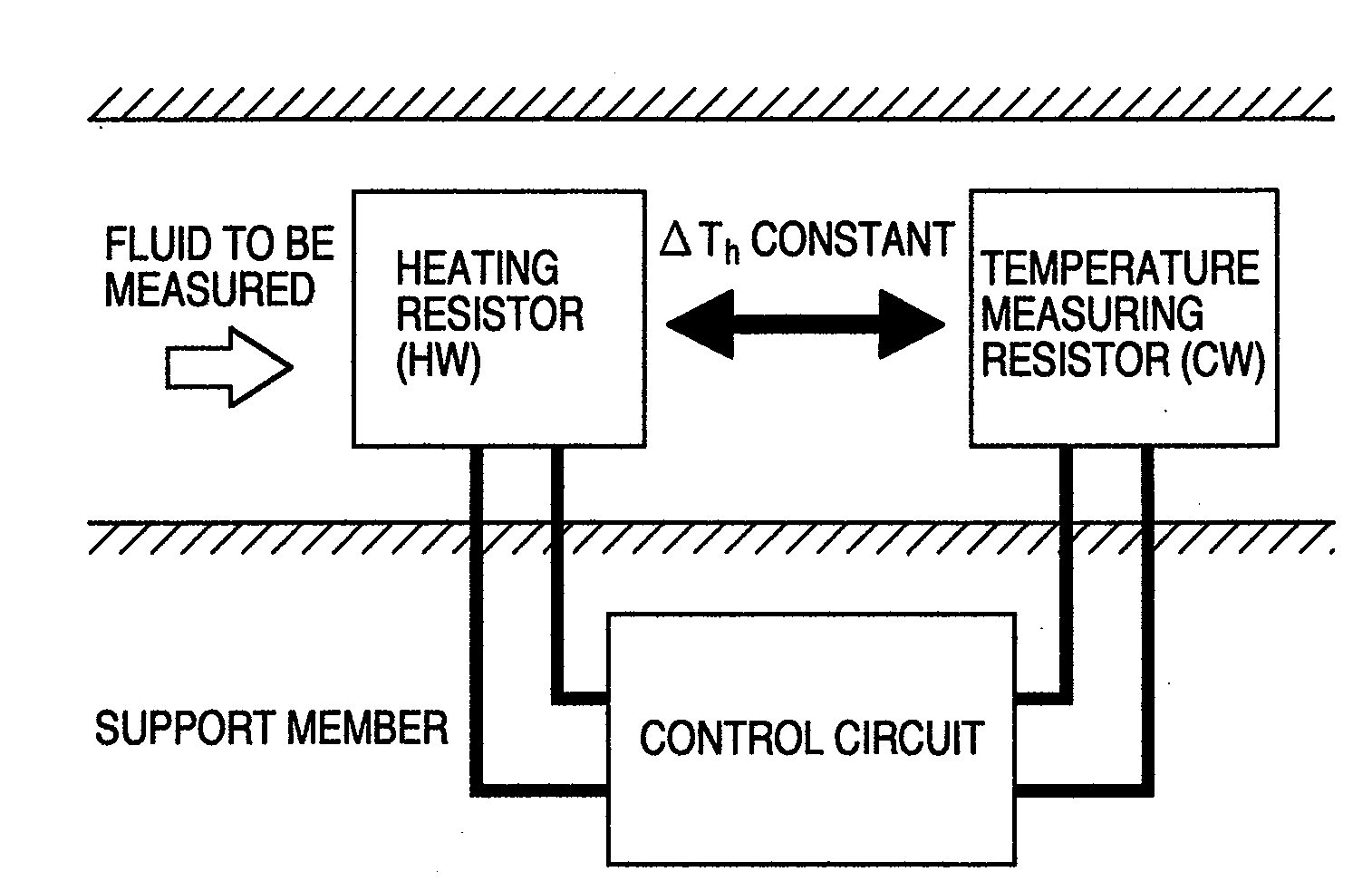
[0049]Referring first to FIGS. 1 and 2, the principle of a thermal type flow meter representing the leading type of intake air flow meter will be described briefly. The thermal type flow meter is constructed as shown in FIG. 1. In the thermal type meter configuration, at least two resistors are disposed in fluid, one of them being used as a temperature measuring resister for detecting temperatures of the fluid with the other as a heating resister for detecting the flow rate, and a temperature difference (ΔTh) between these resistors is always kept to be constant so as to realize measurement of mass flow rates of the fluid. Then, in the intake air flow meter, by totally judging the measurement accuracy, responsibility, prevention of contamination attributable to dust and durability or heat-proof capability of a material used, ΔTh is set in general to about 200° C.

[0050]A bridge control circuit configured as shown in FIG. 2 is used. The heating resistor and temperature measuring resis...


PUM


Abstract

A thermal type flow meter has a first heating resistor, a second heating resistor for blocking heat transfer from the first heating resistor to a console, a temperature measuring resistor interposed between the two heating resistors, and a controller for calculating a flow rate unrelated to temperatures of fluid from temperatures of the resistors and currents supplied to the heating resistors.

Description

BACKGROUND OF THE INVENTION[0001]The present invention relates to a thermal type flow meter for detecting flow rates of intake and exhaust gas of an engine and its control method.[0002]In a thermal type flow meter as shown in FIG. 1, at least two resistors are disposed in fluid, one of them being used as a temperature measuring resister (CW) for detecting temperatures of the fluid with the other as a heating resister (HW) for detecting flow rates, and the temperature difference (ΔTh) between these resistors is always kept to be constant so as to realize measurement of mass flow rates of the fluid.[0003]This type of thermal flow meter faces a problem that because of the independently separate arrangement of heating resistor and temperature measuring resistor in the fluid, the installation space increases, the pressure loss increases and the production cost is high.[0004]In general, the temperature measuring resistor adapted to detect fluid temperatures is not heated normally by condu...

Claims


Application Information

Patent Timeline
Patent Type & Authority Applications(United States)
IPC IPC(8): G01F1/692
CPCG01F1/688G01F1/6983
Inventor SUKEGAWA, YOSHIHIROTOKUYASU, NOBORUHOSHIKA, HIROAKI
Owner HITACHI LTD
Why Eureka
Try Eureka