Parallel Flow Heat Exchanger For Heat Pump Applications

a heat exchanger and parallel flow technology, applied in the field of refrigerant heat pump systems, can solve the problems of extreme limit of their application in the heat pump field, difficulty in achieving the effect of equal design, poor reliability, etc., to improve reliability, enhance heat pump system performance, and enhance performan

Active Publication Date: 2008-12-04
CARRIER CORP
View PDF9 Cites 57 Cited by
  • Summary
  • Abstract
  • Description
  • Claims
  • Application Information

AI Technical Summary

Benefits of technology

[0014]It is the object of the present invention to provide for a parallel flow heat exchanger construction which exhibits performance advantages, particularly in the heat pump installations, by employing converging and / or diverging circuits and consequently providing adequate balancing of refrigerant heat transfer and pressure drop characteristics. It is another object of the present invention to provide for a parallel flow heat exchanger system design incorporating variable length circuits, including the capability for a refrigerant flow reversal, to enhance heat pump system performance while switching between and operating in both cooling and heating modes.
[0015]In one embodiment, a heat exchanger system design includes a parallel flow heat exchanger having two refrigerant passes while operating as a condenser and a single refrigerant pass while operating as an evaporator. In the condenser operation, the refrigerant is delivered to an inlet manifold and distributed to a larger number of parallel heat exchange tubes in the first path, collected in the intermediate manifold and then delivered to the outlet manifold through a smaller remaining number of parallel heat exchange tubes as will be described in greater detail hereinafter. In the evaporator operation, by utilizing a check valve system and routing piping, the refrigerant flow through the parallel flow heat exchanger is reversed and arranged in a single-pass configuration, while a single expansion device is provided to expand refrigerant to a lower pressure and temperature upstream of the evaporator. Therefore, the aforementioned benefits of enhanced performance and improved reliability are achieved in both cooling and heating modes of operation due to an optimal balance between refrigerant heat transfer and pressure drop characteristics inside the heat exchange tubes.
[0016]In another embodiment, a heat exchanger system includes a separate intermediate manifold and a parallel flow heat exchanger operating as a three-pass condenser and a single-pass evaporator. Operation and obtained advantages of this system are analogous to the previous embodiment. Furthermore, multiple expansion devices are provided to avoid or diminish effects of refrigerant maldistribution.
[0017]In still another embodiment, a heat exchanger system incorporates a parallel flow heat exchanger having three passes in the condenser operation while having only a single pass in the evaporator duty. This embodiment includes a single expansion device and a distributor system that can improve refrigerant distribution as well.

Problems solved by technology

Parallel flow heat exchangers started to gain popularity in the air conditioning installations but their application in the heat pump field is extremely limited for the reasons outlined below.
Consequently, heat exchanger and heat pump system designers face a challenge to optimize the heat exchanger circuiting configuration for performance in both cooling and heating modes of operation.
This becomes a particularly difficult task, since an adequate balance between refrigerant heat transfer and pressure drop characteristics is to be maintained throughout the heat exchanger.
Therefore, many heat pump heat exchanges are designed with an equal, although not optimal, number of straight-through circuits for both cooling and heating modes of operation.
In the parallel flow heat exchangers, due to the design particulars as well as manifold design and refrigerant distribution specifics, the number of parallel circuits can be altered only at the manifold locations, restricting heat exchanger design flexibility, especially in the heat pump applications.
Consequently, implementation of a variable number of parallel circuits along the heat exchanger length as well as variable length circuits for cooling and heating modes of operation represent a significant obstacle for heat exchanger and heat pump system designers and is not known in the art of parallel flow heat exchangers.
Another challenge a heat exchanger designer faces is refrigerant maldistribution, especially pronounced in the refrigerant system evaporators.
It causes significant evaporator and overall system performance degradation over a wide range of operating conditions.
Maldistribution of refrigerant may occur due to differences in flow impedances within evaporator channels, non-uniform airflow distribution over external heat transfer surfaces, improper heat exchanger orientation or poor manifold and distribution system design.
Attempts to eliminate or reduce the effects of this phenomenon on the performance of parallel flow evaporators have been made with little or no success.
The primary reasons for such failures have generally been related to complexity and inefficiency of the proposed technique or prohibitively high cost of the solution.
As mentioned above, in the heat pump systems, each parallel flow heat exchanger is utilized as both a condensers and an evaporator, depending on the mode of operation, and refrigerant maldistribution is one of the primary concerns and obstacles for the implementation of this technology in the evaporators of the heat pump systems.
Refrigerant maldistribution in parallel flow heat exchangers occurs because of unequal pressure drop inside the channels and in the inlet and outlet manifolds, as well as poor manifold and distribution system design.
Furthermore, the recent trend of the heat exchanger performance enhancement promoted miniaturization of its channels (so-called minichannels and microchannels), which in turn negatively impacted refrigerant distribution.
Since it is extremely difficult to control all these factors, many of the previous attempts to manage refrigerant distribution, especially in parallel flow evaporators, have failed.
Since both phases flow independently, refrigerant maldistribution tends to occur, potentially causing the two-phase (zero superheat) conditions at the exit of some heat transfer tubes and promoting flooding at the compressor suction that may quickly translate into the compressor damage.
Thus, a designer of parallel flow heat exchangers for the heat pump applications faces the following challenges: implementation of the variable length diverging and conversing circuits for improving performance characteristics in the heating and cooling modes of operation, handling the reversed flow and avoiding maldistribution (as well as and other reliability issues such as oil holdup).

Method used


Image

  • Parallel Flow Heat Exchanger For Heat Pump Applications
  • Parallel Flow Heat Exchanger For Heat Pump Applications
  • Parallel Flow Heat Exchanger For Heat Pump Applications

Examples


Embodiment Construction

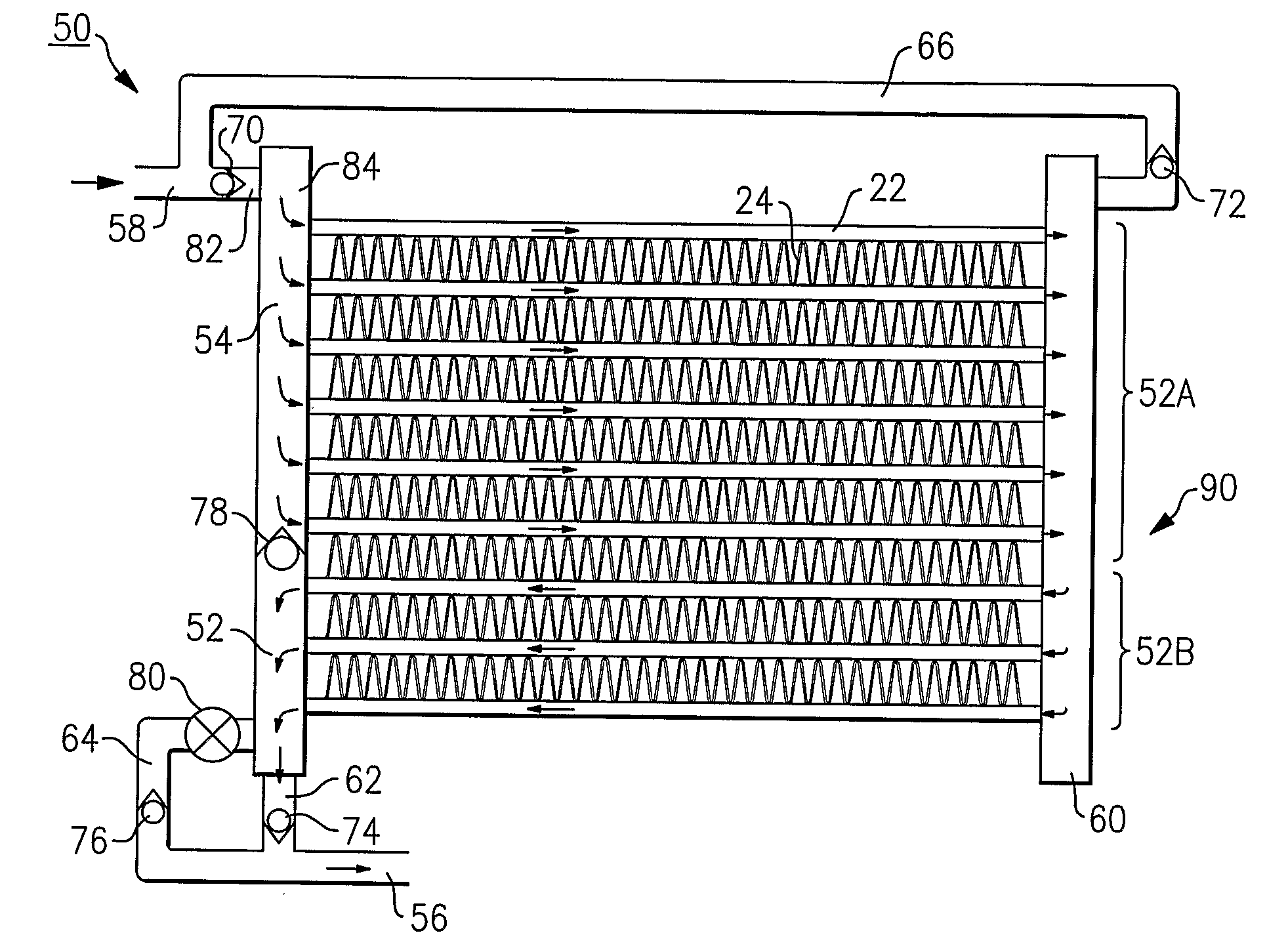
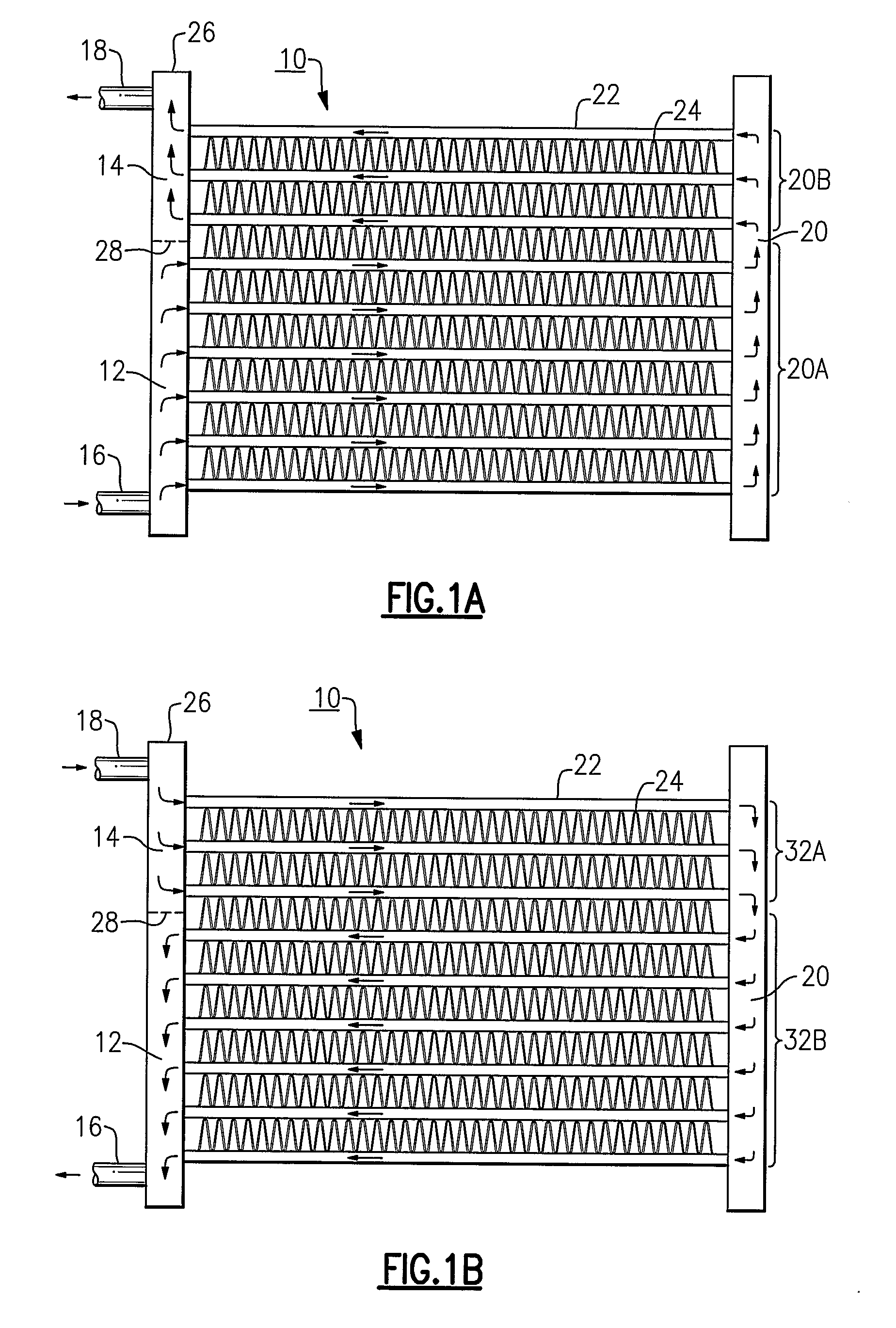
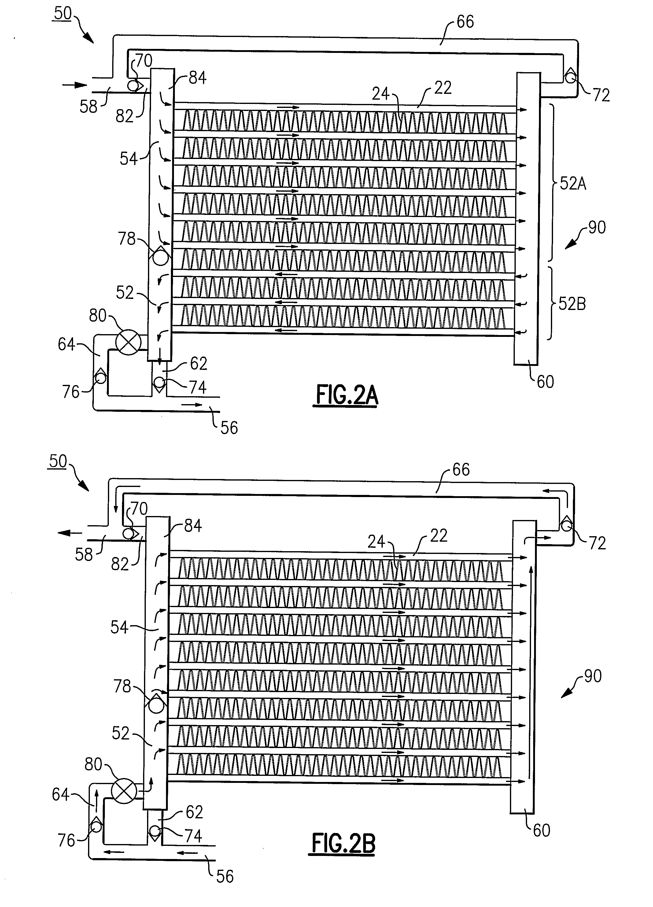
[0027]In the operation of a conventional parallel flow heat exchanger, refrigerant flows through the inlet opening and into the internal cavity of an inlet manifold. From the inlet manifold, the refrigerant, in a single-pass configuration, enters and passes through a series of parallel heat transfer tubes to the internal cavity of an outlet manifold. Externally to the tubes, air is circulated over the heat exchange tubes and associated airside fins by an air-moving device such as fan, so that heat transfer interaction occurs between the air flowing outside the heat transfer tubes and refrigerant inside the tubes. The heat exchange tubes can be hollow or have internal enhancements such as ribs for structural rigidity and heat transfer augmentation. These internal enhancements divide each heat exchange tube into multiple channels along which the refrigerant is flown in a parallel manner. The channels typically have circular, rectangular, triangular, trapezoidal or any other feasible c...


PUM


Abstract

A parallel flow heat exchanger system (10, 50, 100, 200) for heat pump applications in which single and multiple paths of variable length are established via flow control systems which also allow for refrigerant flow reversal within the parallel flow heat exchanger system (10, 50, 100, 200), while switching between cooling and heating modes of operation. Examples of flow control devices are an expansion device (80) and various check valves (70, 72, 74, 76). The parallel flow heat exchanger system may have converging or diverging flow circuits and may constitute a single-pass or a multi-pass evaporator together with and a multi-pass condenser.

Description

CROSS-REFERENCE TO RELATED APPLICATION[0001]Reference is made to and this application claims priority from and the benefit of U.S. Provisional Application Ser. No. 60 / 649,382, filed Feb. 2, 2005, and entitled PARALLEL FLOW HEAT EXCHANGERS FOR HEAT PUMP APPLICATIONS, which application is incorporated herein in its entirety by reference.BACKGROUND OF THE INVENTION[0002]This invention relates generally to refrigerant heat pump systems and, more particularly, to parallel flow heat exchangers thereof.[0003]A definition of a so-called parallel flow heat exchanger is widely used in the air conditioning and refrigeration industry and designates a heat exchanger with a plurality of parallel passages, among which refrigerant is distributed and flown in the orientation generally substantially perpendicular to the refrigerant flow direction in the inlet and outlet manifolds. This definition is well adapted within the technical community and will be used throughout the text. Parallel flow heat e...

Claims


Application Information

Patent Timeline
Patent Type & Authority Applications(United States)
IPC IPC(8): F28F9/02
CPCF25B13/00F25B39/00F25B41/04F28D1/05375F28F27/02F25B41/20F28F9/02F28F27/00F25B27/00
Inventor TARAS, MICHAEL F.LIFSON, ALEXANDER
Owner CARRIER CORP
Why Eureka
Try Eureka