Composite Light Guiding Device

Active Publication Date: 2008-12-04
DESIGN LED PRODS
View PDF8 Cites 22 Cited by
  • Summary
  • Abstract
  • Description
  • Claims
  • Application Information

AI Technical Summary

Benefits of technology

[0007]The arrangement of the guide substrate provides a light guiding device that exhibits enhanced mechanical protection for the light sources. Furthermore, since there is no air gap between the output of the light sources and the guide substrate the guide substrate provides a device that is simple to produce and which exhibits enhanced optical coupling of the light within the device. Employing a transparent substrate also provides for increased flexibility for the device i.e. the choice of output surface, creation of independent light controlled areas.
[0013]Preferably the one or more blocking regions comprise an opaque sheet located on the first surface. Most preferably the opaque sheet comprises one or more apertures that define one or more interaction regions of the device. This arrangement allows for a compact device to be produced within which each separate interaction region can be employed to provide independent illumination, backlighting, signage or display functions.
[0014]Optionally the one or more light sources comprise a non-directional source of light. In such embodiments the light guiding device further comprises a reflecting structure located on the guide substrate so as to redirect the light produced by the one or more non-directional sources of light over the first surface. Preferably the reflecting structure comprises a refractive or diffractive optical element so as to maximise the amount of light redirected over the first surface.

Problems solved by technology

It will be appreciated by those skilled in the art that the integration of fluorescent lamps or LEDs to the edge of the transparent light guide is not a straightforward process and thus significantly increases the complexity of the production process for these devices.
In addition, edge coupling of the light sources renders these components susceptible to mechanical damage during both the production process and the normal use of the device.

Method used


Image

  • Composite Light Guiding Device
  • Composite Light Guiding Device
  • Composite Light Guiding Device

Examples


Embodiment Construction

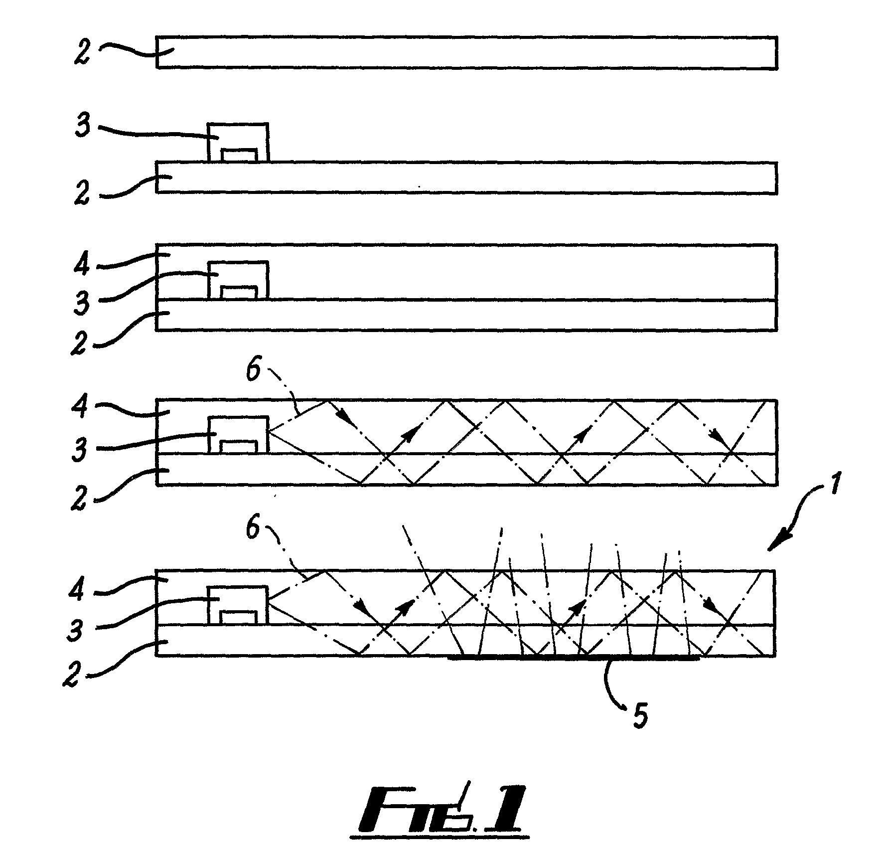
[0042]In order to assist understanding of various aspects of the present invention, FIGS. 1 to 6 present a number alternative embodiments of a composite light guiding device 1. The terms “transparent” and “opaque” employed throughout the following description relate to the optical properties of particular components of the device relative to the wavelength of the light generated by the incorporated light sources.

[0043]Referring initially to FIG. 1, a side elevation of the composite light guiding device 1 at various stages of production is presented. The composite light guiding device 1 comprises a transparent base substrate 2 made from a transparent polymer sheet, such as polyester or polycarbonate and having a refractive index n2 between 1.50 and 1.58. On top of the transparent base substrate 2 is bonded a light source 3 in the form of an LED. Covering the LED 3 and the remaining area of the top surface of transparent base substrate 2 is a transparent guide substrate 4, also formed...


PUM


Abstract

A light guiding device (1) and in particular to a light guiding device that can be used for illumination, backlighting, signage or display purposes is described. The light guiding device (1) comprises a transparent base substrate (2), upon a first surface of which are mounted light sources (3), and a guide substrate (4) arranged so as to encapsulate the light sources (3) upon the first surface. In this way the guide substrate (4) provides a means for guiding light produced by the one or more light sources over the first surface. The incorporation of scattering structures (5) along with appropriate choice of the refractive indices of the various layers provides a highly flexible light guiding device that is typically less than 1 mm thick. The described light guiding device (1) provides particular application as a seven segment display.

Description

[0001]The present invention relates to a light guiding device and in particular to a light guiding device that can be used for illumination, backlighting, signage or display purposes.[0002]A number of light guiding devices are known to those skilled in the art. These devices are employed for a range of functions including illumination, backlighting, signage and display purposes. Typically, the devices are constructed from an injection moulded or machined transparent plastic component, where a light source, such as a fluorescent lamp or a plurality of LEDs, is integrated by means of mechanical attachment at the edge of the transparent plastic component. Examples of such devices are provided by the authors within PCT Publication No. 2005 / 101070.[0003]Common to all of these devices is the fact that light from the light source is guided through a transparent guide, typically made of plastic, by total internal reflection. For backlighting applications, light is emitted in a substantially...

Claims


Application Information

Patent Timeline
IPC IPC(8): F21V8/00B29D11/00
CPCG02B6/0021G02B6/0028G02B6/0043G02B6/006G02B6/0068G02B6/0073G02B6/12004G02B6/0011G02B6/0081G02B6/42G09F13/18
Inventor GOURLAY, JAMES
Owner DESIGN LED PRODS
Why Eureka
Try Eureka