Flickerless light source

a fluorescent light source and light tube technology, applied in the field of light sources, can solve the problems of light tube explosion, difficult to maintain a stable flow of current, and it takes several seconds for fluorescent light to start emitting ligh

Active Publication Date: 2008-12-04
PIXON TECH CORP
View PDF4 Cites 89 Cited by
  • Summary
  • Abstract
  • Description
  • Claims
  • Application Information

AI Technical Summary

Benefits of technology

[0023]Another advantage of the present invention is that the light source of the present invention isn't pressurized. As a result, the light source of the present invention can't explode like a conventional fluorescent light tube.
[0024]These and other objectives of the present invention will become obvious ...

Problems solved by technology

One disadvantage is that it can take several seconds for the fluorescent light to start emitting light.
Another disadvantage is that it is difficult to maintain a stable flow of current through the gas which in some cases can cause the light tube to explode or can destroy other components in the circuit.
Unfortunately, this causes the light to flicker which is annoying and irritating.
Additionally, the ballast 140 can vibrate at a low frequency which is audible to hum...

Method used


Image

  • Flickerless light source
  • Flickerless light source
  • Flickerless light source

Examples


Embodiment Construction

[0038]Reference will now be made in detail to the preferred embodiments of the present invention, examples of which are illustrated in the accompanying drawings. Wherever possible, the same reference numbers are used in the drawings and the description to refer to the same or like parts.

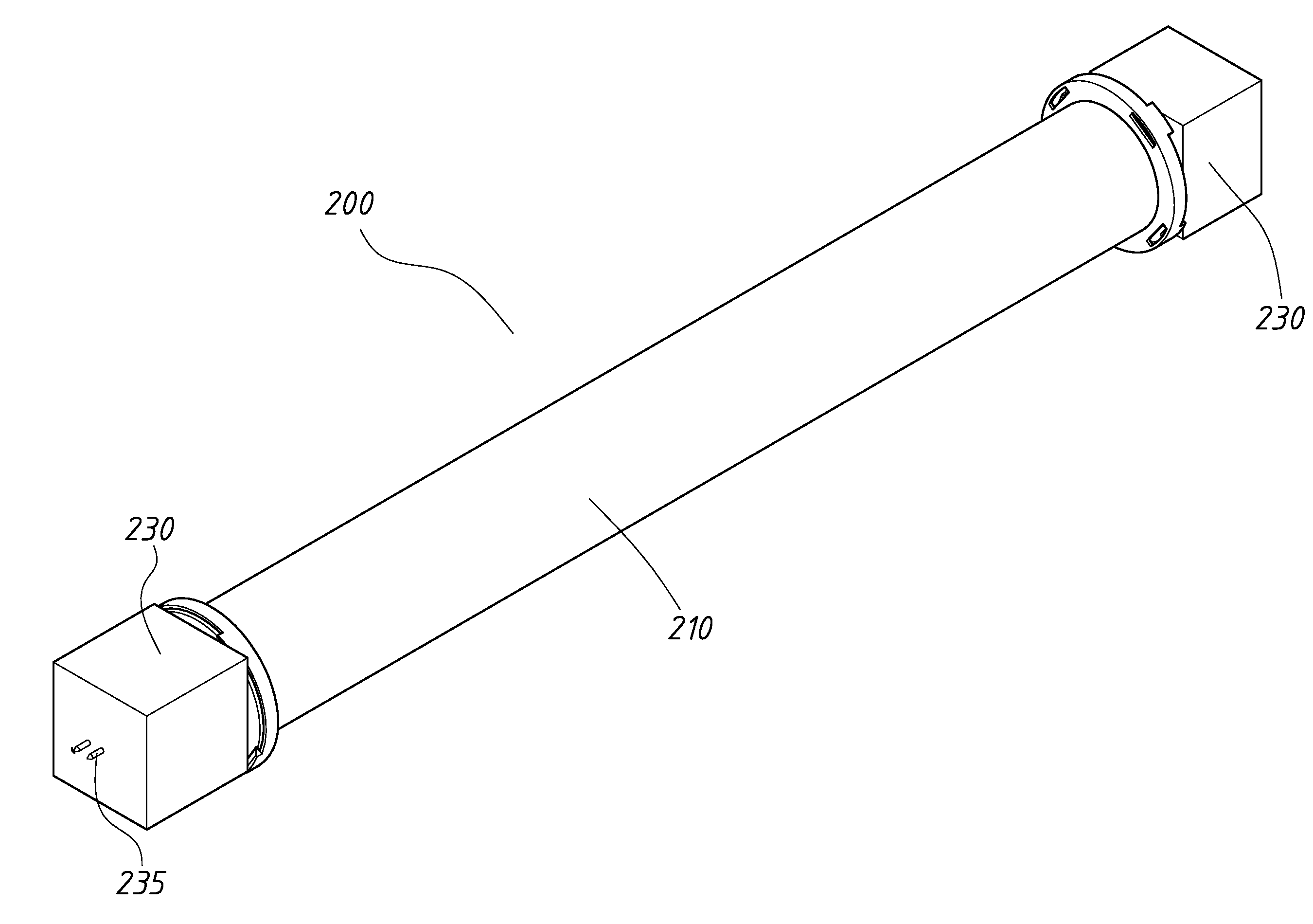
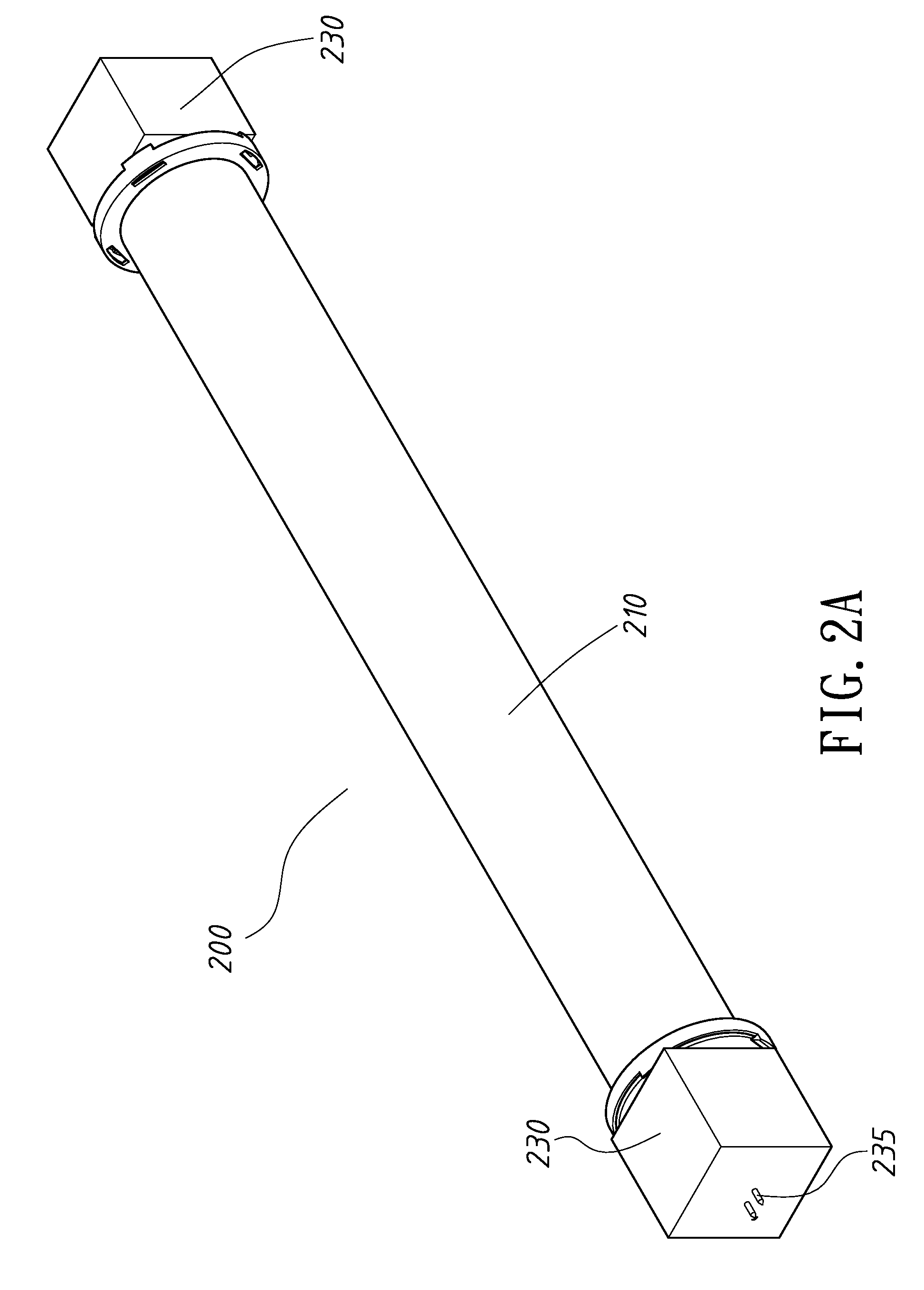
[0039]Refer to FIG. 2A, which is a drawing illustrating a flickerless light source according to an embodiment of the present invention, and to FIG. 2B, which is a drawing illustrating an exploded view of a flickerless light source according to an embodiment of the present invention.

[0040]As shown in FIG. 2A and FIG. 2B the flickerless light source 200 comprises a diffuser tube 210, a lightpipe 220 inside the diffuser tube 210, and two LED light sources 230 one on each end of the diffuser tube 210. Each of the LED light sources 230 comprise electrical connectors 235 for allowing power to be applied to the LED light sources 230. A assembly couplers 280 hold the light source assembly together.

[0041]Refe...


PUM


Abstract

A flickerless light source comprising a transparent or semitransparent diffuser, a lightpipe with a patterned surface inside the diffuser, and an LED light source attached to each end of the lightpipe is disclosed. The patterned surface of the lightpipe diffuses or reflects light emitted by the LED light sources and through the lightpipe to provide a light with uniform brightness and intensity. The lightpipe is coated with a thin layer of visible-light transparent material which is doped with organic dye molecules. The organic dye has strong ultraviolet light absorption characteristics. By changing the doping concentration of the dye molecules the coating can become total opaque or semi-transparent to certain wavelengths and selective wavelength conversion is obtained. In this way light color, brightness, and intensity can be varied or controlled.

Description

BACKGROUND OF THE INVENTION[0001]1. Field of the Invention[0002]The present invention relates to a light source. More specifically, the present invention discloses a flickerless light source that is safe to humans, environmentally friendly, and possesses an extremely long lifetime.[0003]2. Description of the Prior Art[0004]Fluorescent lights are a commonly used light source. In a fluorescent light an electric current stimulates mercury atoms. This causes the mercury atoms to release ultraviolet photons which stimulate a phosphor. The stimulated phosphor then emits visible light photons.[0005]Refer to FIG. 1, which is a drawing illustrating a conventional fluorescent light installation. As shown in FIG. 1, a conventional fluorescent light installation 100 consists of a sealed glass tube 110 containing a small amount of mercury and inert gas with a phosphor powder coating on the inside of the glass tube 110. An electrode 120 is situated on both ends of the sealed tube 110. A starter 1...

Claims


Application Information

Patent Timeline
IPC IPC(8): G02B5/02G02B6/00
CPCF21K9/52F21Y2101/02F21Y2103/00G02B5/021G02B6/001G02B17/006F21K9/17F21K9/27F21K9/61F21Y2115/10
Inventor WU, RONG-YAWHSU, AI-LAN
Owner PIXON TECH CORP
Why Eureka
Try Eureka