Positioning device and method for positioning a load

Active Publication Date: 2008-12-11
VARIAN MEDICAL SYST PARTICLE THERAPY GMBH & CO KG
View PDF5 Cites 42 Cited by
  • Summary
  • Abstract
  • Description
  • Claims
  • Application Information

AI Technical Summary

Benefits of technology

[0022]The ascertained loading of the positioning device may be subjected

Problems solved by technology

In positioning the patient, the weight of the patient may cause elastic deformation that leads to imprecise positioning.
However, the more-rigid construction resu

Method used


Image

  • Positioning device and method for positioning a load
  • Positioning device and method for positioning a load
  • Positioning device and method for positioning a load

Examples


Embodiment Construction

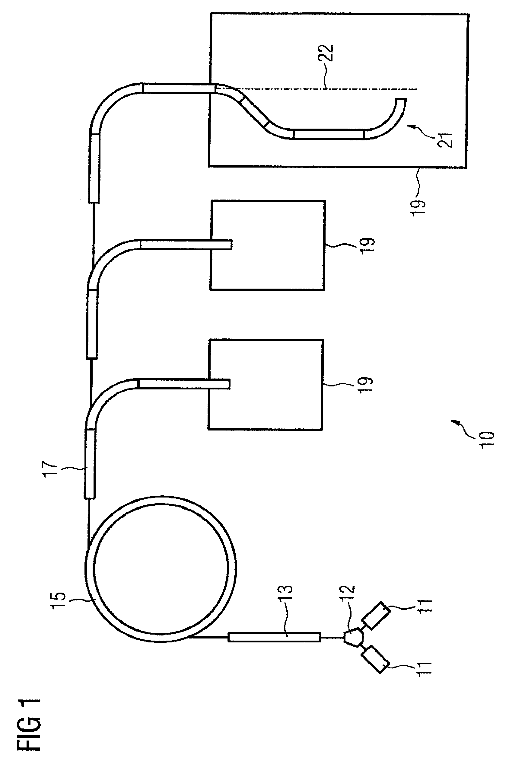
[0029]FIG. 1 shows a particle therapy system 10. The particle therapy system 10 may be used to irradiate a body, such as tissue diseased by tumor, with a particle beam.

[0030]The particles may be ions, protons, pions, helium ions, carbon ions, or other types of ions. The particles may be generated in a particle source 11. If, as shown in FIG. 1, there are two particle sources 11, which generate different types of particles, then a fast switchover between these two types of particles is possible. A switching magnet 12 may be, for example, used for the fast switchover. The switching magnet 12 is located between the particle sources 11 and a preaccelerator 13. For example, the particle therapy system 10 may, for example, be operated with protons and with carbon ions simultaneously.

[0031]The ions generated by the ion source or one of the particle sources 11, and optionally selected with the switching magnet 12, are accelerated to a first energy level in the preaccelerator 13. The preacce...


PUM


Abstract

A positioning device for positioning a load is provided. The positioning device includes a motor, a measuring device, and an evaluation device. The measuring device is associated with the motor, and is operable to ascertain measurement data that characterizes the motor current consumption by the motor in the positioning of the load. The evaluation device evaluates the measurement data that have been ascertained by the measuring device, so that in that way the loading of the positioning device by the load can be ascertained.

Description

[0001]This application claims the benefit of DE 10 2007 026 114.6 filed Jun. 5, 2007, which is hereby incorporated by reference.BACKGROUND[0002]The present embodiments relate to positioning a load.[0003]During particle therapy, a particle beam, for example, including protons or heavy ions, is generated in an accelerator. The particle beam is carried in a radiation channel from the accelerator to an exit window of the radiation channel. The particle beam enters an irradiation or treatment room through the exit window. The particle beam may be used to treat cancer.[0004]The success of tumor treatment depends on the precision of the tumor positioning. Positioning a patient depends on a plurality of factors. For example, the precision of positioning depends on how the patient is supported and the rigidity of the patient support system. In positioning the patient, the weight of the patient may cause elastic deformation that leads to imprecise positioning.[0005]A more-rigid construction m...

Claims


Application Information

Patent Timeline
IPC IPC(8): A61G7/00G06F17/00G01B7/00
CPCA61B6/0457A61B6/5276A61G13/02A61G13/04A61G13/06B25J9/1669G05B2219/40042G05B2219/40453G05B2219/40461G05B2219/45117A61B6/4092A61N5/1049A61N2005/1057A61B6/0487B25J9/1638G05B2219/35285G05B2219/37285G05B2219/39176G05B2219/49189
Inventor FAHRIG, WOLFRAMHERRMANN, KLAUSLOSEKEN, JOCHEN MIGUEL
Owner VARIAN MEDICAL SYST PARTICLE THERAPY GMBH & CO KG
Why Eureka
Try Eureka