Glow plug and method of manufacturing the same

a technology of glow plugs and plugs, which is applied in the field of glow plugs, can solve the problems of increasing rush current and increasing rush current, and achieve the effect of reducing power consumption and high reliability

Inactive Publication Date: 2008-12-11
DENSO CORP
View PDF0 Cites 11 Cited by
  • Summary
  • Abstract
  • Description
  • Claims
  • Application Information

AI Technical Summary

Benefits of technology

[0032]With the method of manufacturing a glow plug according to a second aspect of the present invention, the glow plug can be manufactured on mass production in a highly reliable manner. The glow plug has rush current that is minimized to a level less than 45 A even when applied

Problems solved by technology

That is, the use of the heating element having a low initial resistance and large temperature coefficient of resistance results in an increase in rush current.
Thus, the battery capacity of the related art battery is insufficient in providing electric power for a starter of the engine to be driven, causing a fear to arise with an unsuccessful result in startup.
This causes the

Method used


Image

  • Glow plug and method of manufacturing the same
  • Glow plug and method of manufacturing the same
  • Glow plug and method of manufacturing the same

Examples


first embodiment

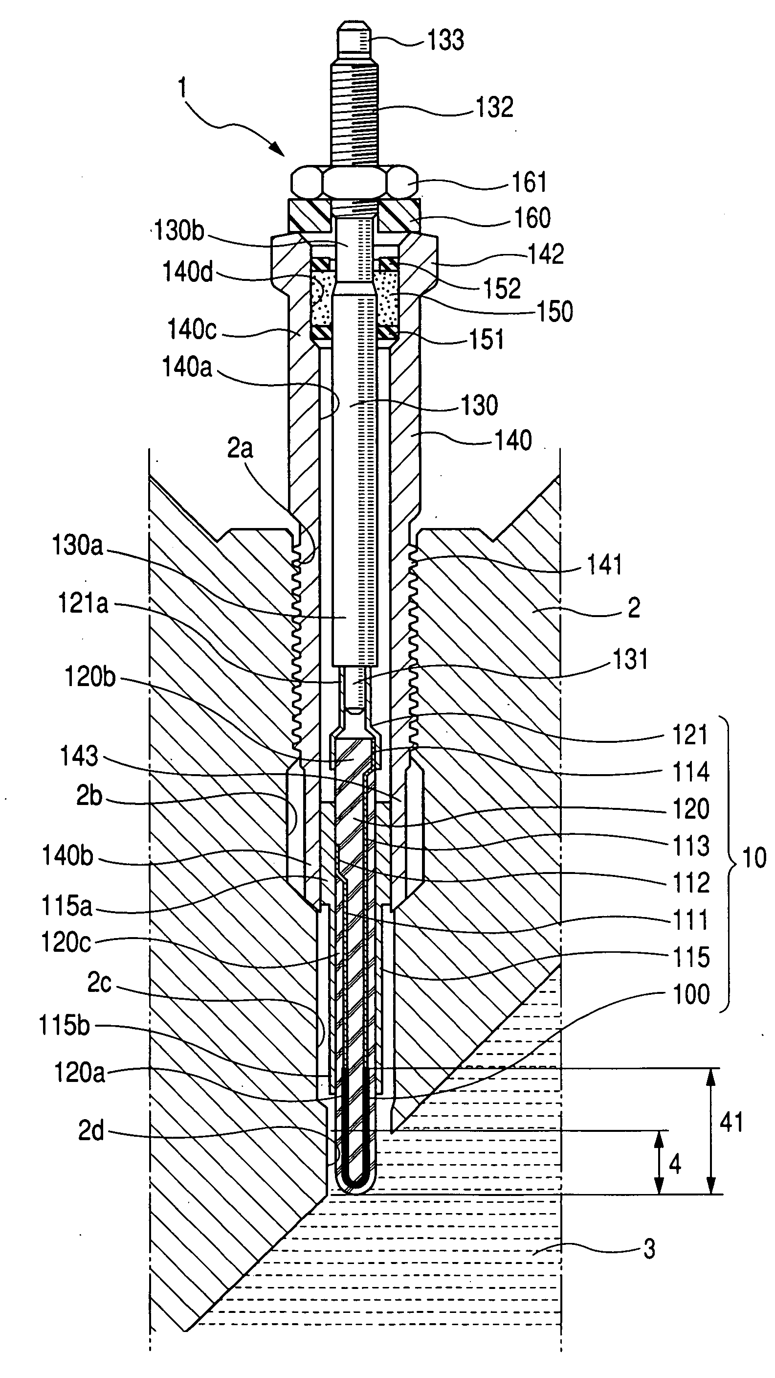
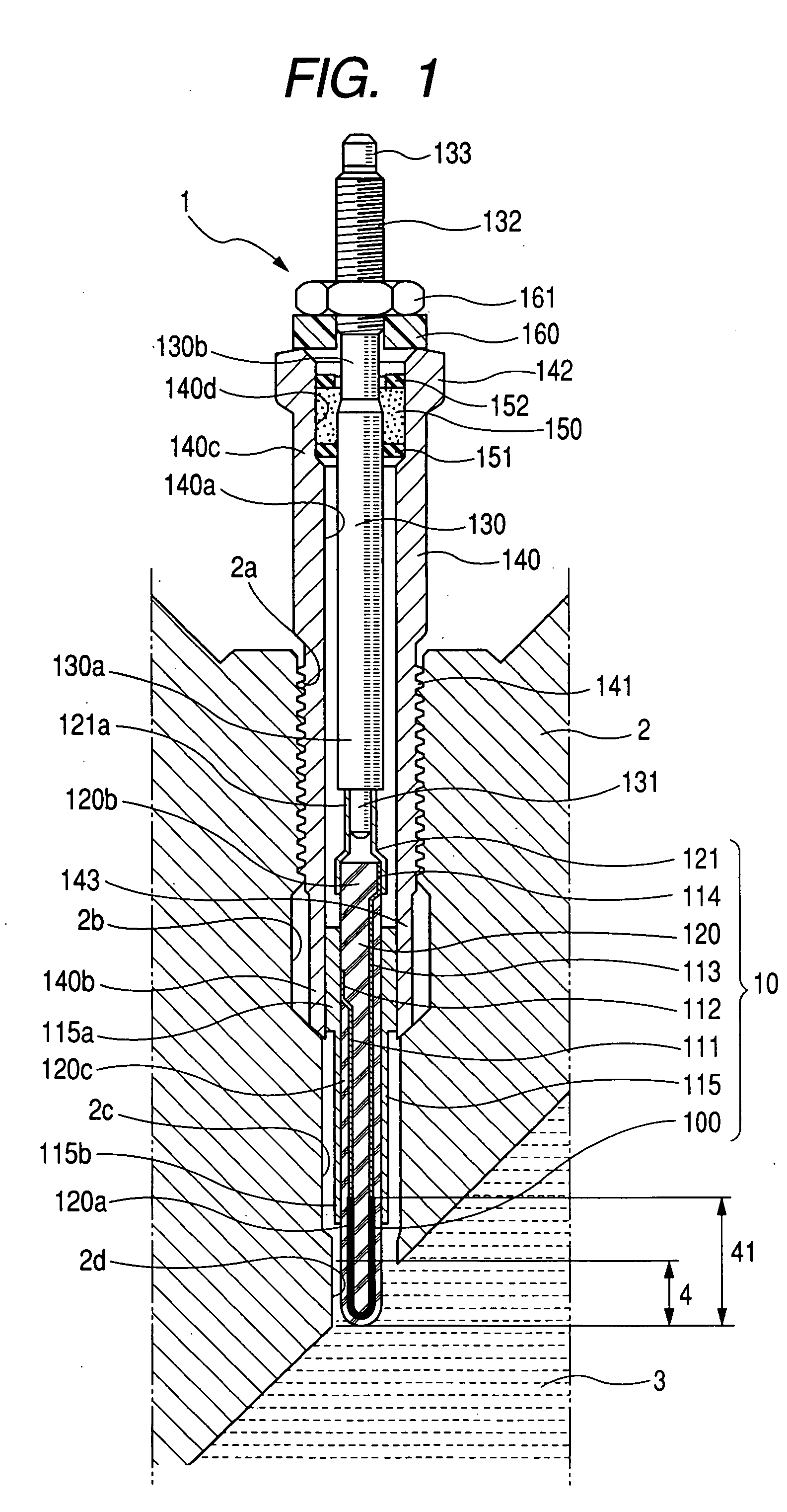
[0047]Now, a glow plug 1 of a first embodiment according to the present invention is described below in detail with reference to a structure under which the glow plug 1 is mounted on an engine head 2.

[0048]As shown in FIG. 1, the glow plug 10 is suitably applied to, for instance, the engine head 2 of an automotive engine for each cylinder to preheat a combustion chamber 3 of the engine for promoting in ignition and combustion of air fuel mixture on or after startup of the engine.

[0049]In particular, the engine head 2 has a threaded bore 2a, a large-diameter intermediate bore 2b, a small-diameter bore 2c and an end bore 2d, which are coaxially formed in connection to the combustion chamber 3.

[0050]The glow plug 1 includes a housing 140 having an intermediate portion formed with a threaded portion 141. The threaded portion 141 of the housing 140 is screwed into the threaded bore 2a of the engine head 2 to be fixedly mounted thereon. The housing 140 has an axially extending internal bo...


PUM

PropertyMeasurementUnit
Temperatureaaaaaaaaaa
Lengthaaaaaaaaaa

Abstract

A glow plug and related manufacturing method are disclosed. The glow plug includes a heating section for heating a combustion chamber of an engine for promoting an ignition. The heating section includes a ceramic heating element developing a heat when applied with electric power, a ceramic insulating support body embedded with the heating element, and a pair of lead wires connected to the heating element and having terminal portions exposed to a surface of the insulating body. The heating element has a positive temperature coefficient of resistance and includes: (a) initial resistance R20 equal to or greater than 0.3Ω and equal to or less than 0.65Ω; (b) heating resistance R1200 equal to or greater than 0.7Ω and equal to or less than 1.3Ω; and (c) temperature coefficient of resistance R1200/R20 equal to or greater than 2.0 and equal to or less than 4.0.

Description

CROSS REFERENCE TO RELATED APPLICATIONS[0001]This application is related to Japanese Patent Application No. 2006-270529, filed on Oct. 2, 2006, the content of which is hereby incorporated by reference.BACKGROUND OF THE INVENTION[0002]1. Technical Field of the Invention[0003]The present invention relates to glow plugs for use in internal combustion engines such as diesel engines and, more particularly, to a glow plug for preheating a combustion chamber of an internal combustion engine to promote an ignition of an air fuel mixture.[0004]2. Description of the Related Art[0005]In general, glow plugs have heretofore been widely used in diesel engines and each glow plug has a heating section exposed in a combustion chamber for improving startability of the engine. When applied with electric power, the heating section develops a heat thereby heating the inside of the combustion chamber for assisting an ignition.[0006]In recent years, attempts have heretofore been made to use glow plugs eac...

Claims


Application Information

Patent Timeline
IPC IPC(8): F23Q7/22H05B3/00
CPCF02P19/02H05B3/141Y10T29/49083H05B2203/027H05B3/48
Inventor ANDO, IKUYA
Owner DENSO CORP
Why Eureka
Try Eureka