Eureka AIR delivers breakthrough ideas for toughest innovation challenges, trusted by R&D personnel around the world.

Motor cooling device

Inactive Publication Date: 2008-12-11
DREISON INT
View PDF24 Cites 7 Cited by
  • Summary
  • Abstract
  • Description
  • Claims
  • Application Information

AI Technical Summary

Benefits of technology

[0010]In accordance with another aspect of the present disclosure, a heating system for a vehicle is provided. The heating system comprises a blower assembly, a heater and a static motor cooling device. The blower assembly includes an electric motor, a sealed motor housing for enclosing the electric motor, a drive shaft operably coupled to the electric motor and extending outwardly from the sealed motor housing, and a blower operably connected to the drive shaft. The heater houses a heat exchanger. The blower assembly is mounted to an inlet end section of the heater. The motor cooling device is mounted over the sealed motor housing and passively directs air being drawn into the blower assembly over the motor housing for decreasing the operating temperature of the electric motor with minimal effect on power consumption and air output of the heating system.
[0011]In accordance with yet another aspect of the present disclosure, an airflow system for a vehicle is provided. The airflow system comprises a blower assembly. The blower assembly includes an electric motor, a sealed motor housing for enclosing the electric motor, a drive shaft operably coupled to the electric motor and extending outwardly from the sealed motor housing, and a blower operably connected to the drive shaft. The airflow system further comprises means for passively directing air being drawn into the blower assembly over the motor housing for decreasing operating temperature of the electric motor. The means for directing has minimal effect on power consumption and air output of the heating system.

Problems solved by technology

The motor generates heat, which may be detrimental to the operating life of the motor.
For instance, the motor may have a reduced operating life at higher temperature, or alternatively, the internal components of the motor may burn or melt, thus resulting in premature failure of the motor.
However, vented electric motors cannot be used in certain environments, which require the motor to be protected or sealed.
Although this method provides an effective manner to cool the motor, there is generally a loss in efficiency as air is diverted from the primary discharge purely for motor cooling.
This design is also not compatible with liquid or vapor tight applications; such as in explosive, corrosive, condensing humidity, extremely dusty environments, or those requiring the motor to retain it's operating integrity after having been submerged.
This adds cost, increases package size, and adds an additional load to the motor.

Method used


Image

  • Motor cooling device
  • Motor cooling device
  • Motor cooling device

Examples


Embodiment Construction

[0026]It should, of course, be understood that the description and drawings herein are merely illustrative and that various modifications and changes can be made in the structures disclosed without departing from the present disclosure. It will also be appreciated that the various identified components of the heating assembly and axial fan disclosed herein are merely terms of art that may vary from one manufacturer to another and should not be deemed to limit the present disclosure. All references to direction and position, unless otherwise indicated, refer to the orientation of the motor cooling device illustrated in the drawings and should not be construed as limiting the claims appended hereto.

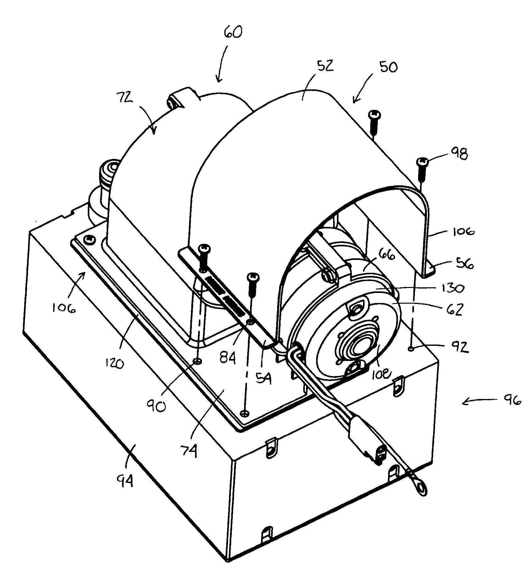
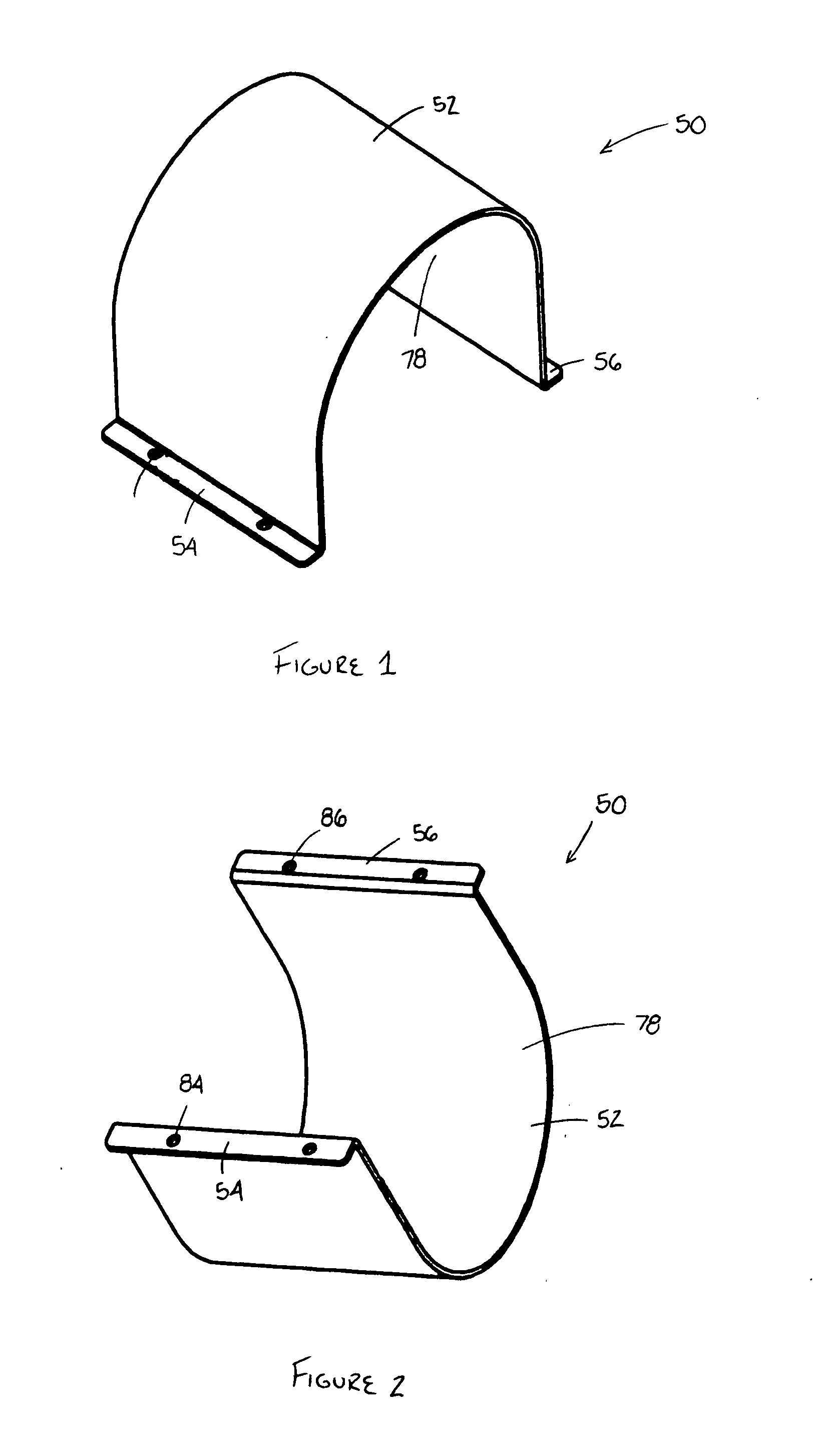
[0027]Referring now to the drawings, wherein like numerals refer to like parts throughout the several views, FIGS. 1 and 2 illustrate a static motor cooling device 50 according to one aspect of the present disclosure. The motor cooling device 50 comprises a shroud 52 and at least one mounti...


PUM


Abstract

A static motor cooling device for a centrifugal blower or axial fan assembly is provided. The blower or fan assembly includes an electric motor, a motor housing for enclosing the electric motor, a drive shaft operably coupled to the electric motor and extending outwardly from the motor housing, and a blower wheel or fan blade operably connected to the drive shaft. The blower or fan includes a blower or fan housing to which the motor housing is at least partially mounted. The motor cooling device comprises a shroud and at least one mounting provision. The motor cooling device is mounted over the motor housing and configured to mate with the blower or fan housing for passively directing a portion of the air being drawn into the blower or fan assembly over the motor housing for cooling the electric motor.

Description

BACKGROUND[0001]The present disclosure relates to an auxiliary, static motor cooling device. It finds particular application in conjunction with centrifugal blowers and axial fans for passively directing air over a drive motor for cooling the drive motor, and will be described with particular reference thereto. However, it is to be appreciated that the present disclosure is also amenable to other like applications.[0002]A blower assembly or axial fan includes an electric drive motor for rotating a blower wheel or fan blade. The motor generates heat, which may be detrimental to the operating life of the motor. For instance, the motor may have a reduced operating life at higher temperature, or alternatively, the internal components of the motor may burn or melt, thus resulting in premature failure of the motor. It is known to provide a flow of air to the drive motor for cooling purposes. This flow of air may be directed in contact with the internal rotating assembly, or be directed in...

Claims


Application Information

Patent Timeline
IPC IPC(8): B60H1/22F24H3/02
CPCF04D25/082F04D29/584Y10T137/85978F04D29/5806
Inventor EUBANK, GERRY E.KOMISARZ, PAUL S.
Owner DREISON INT
Why Eureka
Eureka Blog
Learn More