Wind electrical generation system

a technology of wind power generation and wind power, which is applied in the direction of electric generator control, renewable energy generation, greenhouse gas reduction, etc., can solve the problems of increasing the overall size of the geographical area needed to implement the wind farm, difficult to integrate together into a single overall system, and large propeller-driven wind generators are expensive to build and install. , to achieve the effect of increasing the surface area, increasing the air capture area, and facilitating the flow of air stream

Inactive Publication Date: 2008-12-11
VANGEL PETER D
View PDF32 Cites 8 Cited by
  • Summary
  • Abstract
  • Description
  • Claims
  • Application Information

AI Technical Summary

Benefits of technology

[0005]Briefly, according to an aspect of the invention, a wind electrical generation system includes a relatively large number of small, miniature wind-driven electrical generators or turbines which can be arranged together in one of many various configurations, such as a rack-mounted array. Each generator includes a spinning wheel or disk with a plurality of vanes. Each vane may be formed with a scoop-like configuration near the outer periphery thereof to increase the surface area thereby increasing the air capture area of each vane. An air channel in the form of, e.g., a cylindrical opening or through-hole in the body or frame of the generator facilitates the flow of the air stream through the generator and thus through the overall system. A portion of the outer periphery of each radial vane of each generator

Problems solved by technology

However, despite their increasing popularity, these wind generators have a number of drawbacks.
Also, they tend to be very large (for example, a height of 400 feet and a turbine blade length of 180 feet), and they must be spaced apart by a relatively large distance so as to not affect the proper operation of adjacent or neighboring generators, which increases the overall size of the geographical area needed to implement the wind farm.
Further, these large propeller-driven wind generators are expensive to build and install (particularly for offshore applications), and are difficult to integrate together into a single overall syst

Method used


Image

  • Wind electrical generation system
  • Wind electrical generation system
  • Wind electrical generation system

Examples


Embodiment Construction

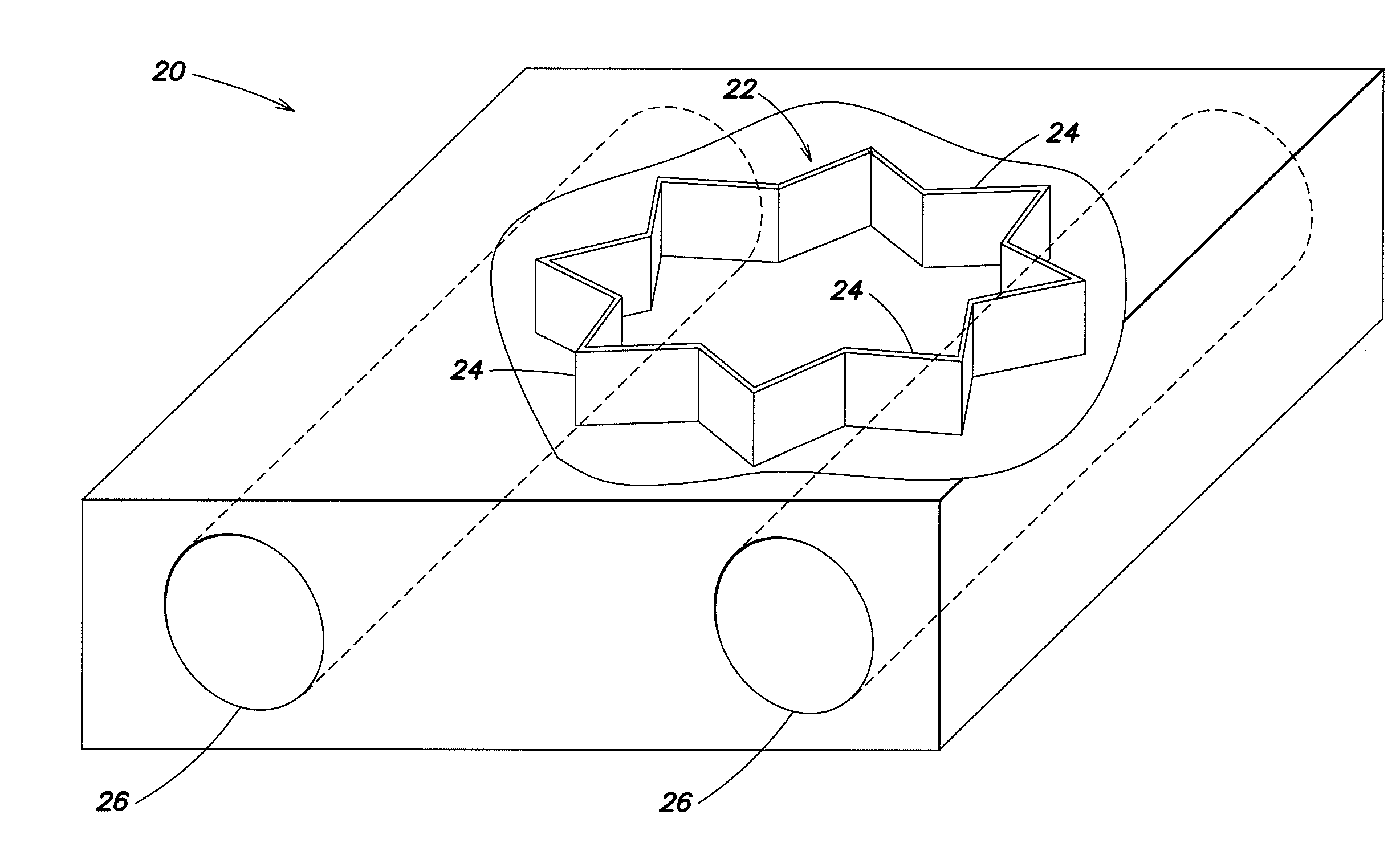
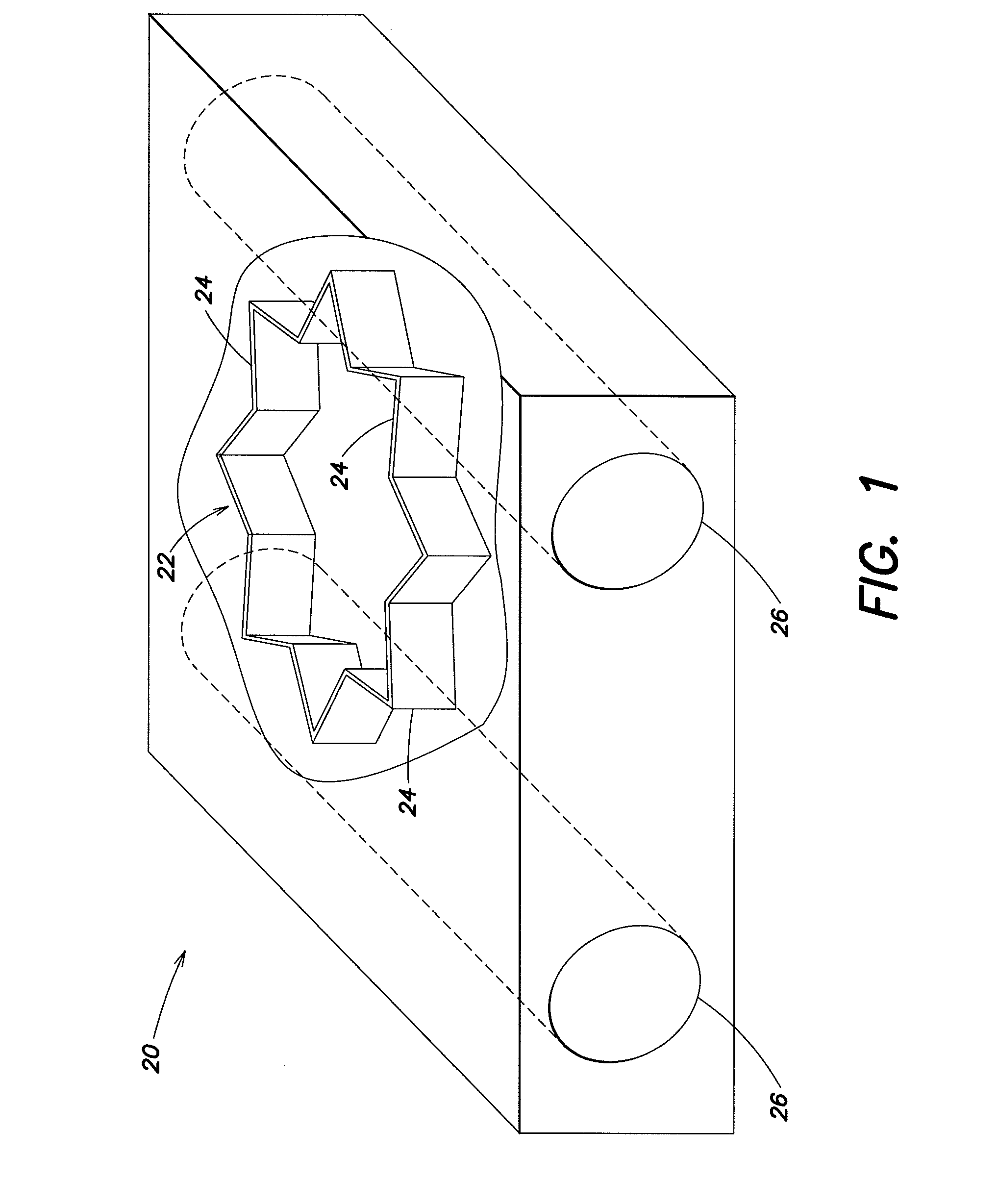
[0018]Referring to FIG. 1, there illustrated is a preferred embodiment of a single, relatively small, miniature electrical generator 20 (“MEG”), a plurality of which are arranged together in a wind electrical generation system of the present invention, described and illustrated in detail hereinafter. Preferably, each MEG 20 may be similar in physical size and structure to the cooling motor or fan (“muffin” fan) used in many types of electronic devices (e.g., personal computers) for cooling of the electronic components of such a device. Thus, the approximate size of the MEG 20 may be three inches wide by three inches high by one inch deep. The muffin fan is typically a low-cost device ($0.50-$2.00 each), is readily available in bulk quantities, operates with little or no noise, and is rugged having a relatively long operational lifetime. The MEG 20 used in the system of the present invention has many of these qualities.

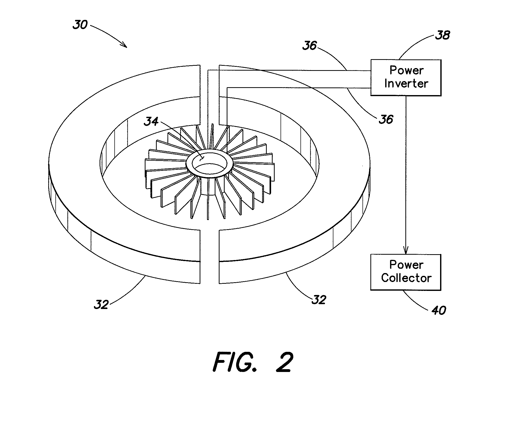
[0019]In the system of the present invention, to operate the MEG ...


PUM


Abstract

A wind electrical generation system includes a relatively large number of small, miniature wind-driven electrical generators or turbines arranged together in various predetermined configurations. Each generator includes a spinning wheel with a plurality of vanes driven by the wind flowing through a plurality of air channels. Each vane may be formed as a scoop to increase the surface area thereby increasing the air capture area of each vane. As each wheel rotates the wheel generates electricity that is captured and utilized for residential and/or commercial use. A control system preferably provides for a constant air velocity and pressure of the air stream in the air channels during operation of the system.

Description

BACKGROUND OF THE INVENTION[0001]The invention relates in general to a wind electrical generation system and in particular to such a system that utilizes a relatively large number of small, miniature wind-driven generators arranged together to provide a source of electricity.[0002]In the art of wind electrical generation systems, it is known to use wind farms that comprise a plurality of relatively large, propeller-driven generators or turbines. These generators are typically located in geographical areas, both onshore and offshore, with certain wind characteristics, for example, an average wind speed of ten mph or greater and a relatively constant wind speed. For each generator, the force or kinetic energy of the wind impinges on the propeller blades causing them to rotate, which causes each corresponding generator to generate electricity that is combined together with that of the other generators and the total electrical power output is then used for various purposes (e.g., region...

Claims


Application Information

Patent Timeline
IPC IPC(8): F03D9/00
CPCF03D3/02F03D3/04F03D5/00F05B2220/20F05B2240/13F05B2240/40F05B2250/131Y02E10/70Y02E10/74F03D9/25
Inventor VANGEL, PETER D.
Owner VANGEL PETER D
Why Eureka
Try Eureka