

Multi-layer magnet arrangement in a permanent magnet machine for a motorized vehicle
a permanent magnet machine and multi-layer technology, applied in the direction of rotating magnets, synchronous machines with stationary armatures, magnetic circuits characterised by magnetic materials, etc., can solve the problems of demagnetization of permanent magnet motors and magnet strength reduction, and achieve the effect of lowering high-temperature stability and magnet strength
- Summary
- Abstract
- Description
- Claims
- Application Information
AI Technical Summary
Benefits of technology
Problems solved by technology
Method used
Image

Examples
Embodiment Construction
[0019]The following detailed description is merely exemplary in nature and is not intended to limit the invention or the application and uses of the invention. Furthermore, there is no intention to be bound by any expressed or implied theory presented in the preceding technical field, background, brief summary or the following detailed description.
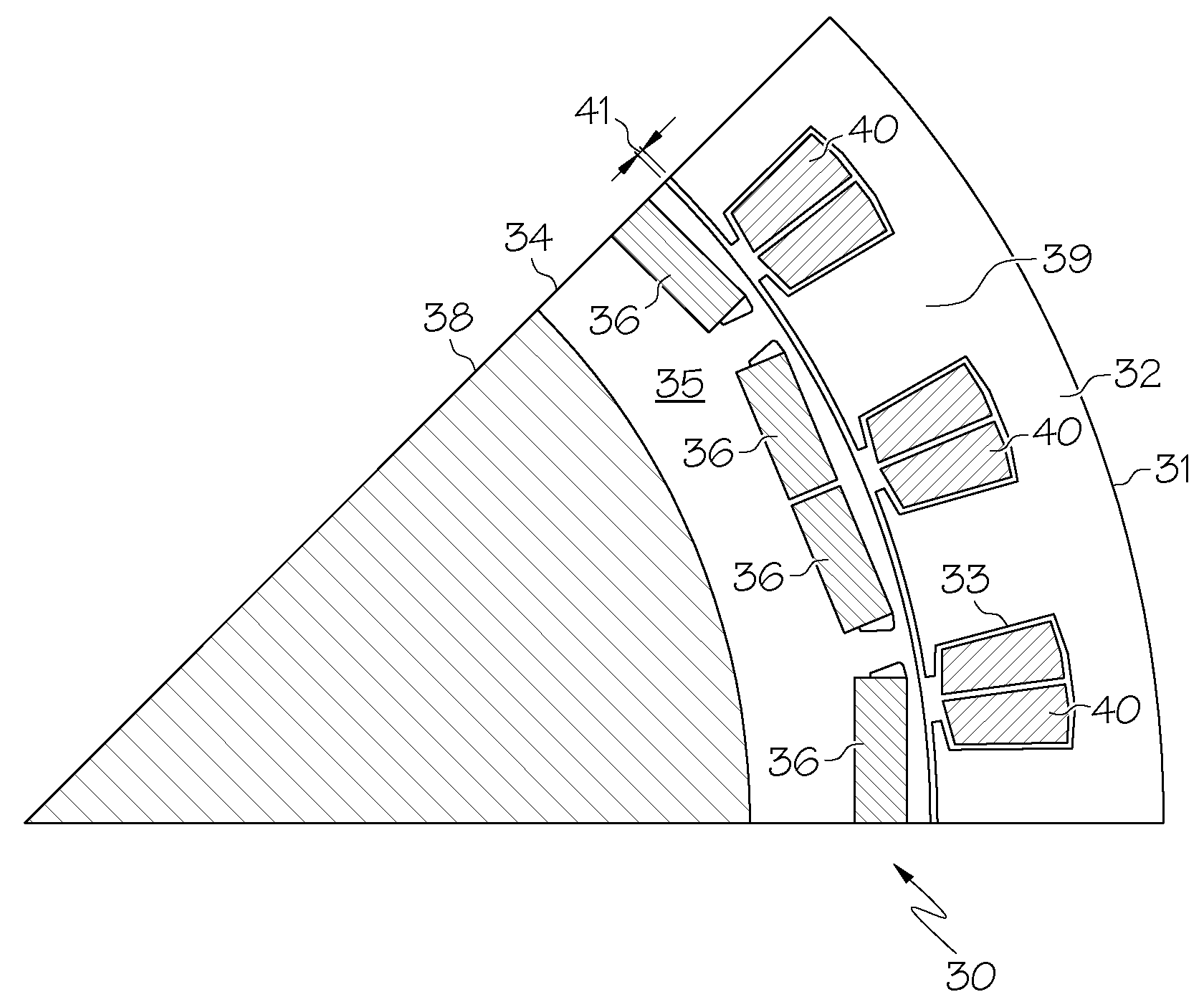
[0020]Turning now to FIG. 2, a partial cross-sectional view is depicted of an embedded permanent magnet machine 30, which may be a component of various automobile components such as a transmission of a hybrid vehicle or a traction system for a fuel cell electric or purely electric vehicle. The permanent magnet machine 30 may also be used in high temperature applications unrelated to motor vehicles. Embodiments that incorporate the principles of the invention include both embedded and surface-mounted permanent magnet machines, of either the concentrated or distributed winding variety. Furthermore, an inside out machine in which the rotor is...
PUM
 Abstract
Description
Claims
Application Information