Antenna Apparatus

a technology of antenna and antenna core, which is applied in the direction of loop antennas with ferromagnetic cores, instruments, transportation and packaging, etc., can solve the problems of reducing the flexibility of the magnetic member, and reducing the mutual inductance necessary for communication, etc., to achieve the effect of high flexibility, low cost and high flexibility

Active Publication Date: 2008-12-11
PANASONIC CORP
View PDF8 Cites 140 Cited by
  • Summary
  • Abstract
  • Description
  • Claims
  • Application Information

AI Technical Summary

Benefits of technology

[0012]The invention can realize a thin-sized antenna apparatus at low cost since a magnetic member having a high flexibility comprising a magnetic ceramic powder is used, a radiating conductor, a terminal electrode and a matching circuit of an antenna are formed at a surface and inside of the magnetic member by a plating transcribing method or a screen printing method, and respective portions can be connected by a via hole. Further, by forming the magnetic member by the magnetic ceramic powder, the flexibility of the magnetic member is much promoted and the antenna apparatus promoting the durability strong at damage or destruction can be constituted.

Problems solved by technology

In a background art, an antenna used in a wireless communication processing apparatus for communicating with a wireless communication medium by an electromagnetic induction system, or the wireless communication medium per se is accompanied by a hazard that the antenna is influenced by a metal present at a surrounding thereof, a magnetic field is weakened, mutual inductance necessary for communication becomes insufficient, a communication distance is shortened or communication cannot be carried out.
Here, when the spacer or the like is used, there poses a problem that adjustment in stalling the spacer and operability involved with the adjustment becomes complicated and further, a shape, particularly a thickness of a total of the antenna is increased and thin-sized formation becomes difficult.
Further, although as the magnetic member, a bulk material of ferrite which is sintered and having a high hardness or the like is used, there poses a problem that the bulk member is inferior in cracking in dropping the magnetic member or a workability thereof.
However, the magnetic body in the flexible shape shown in JP-A-2002-298095 uses sendust, permalloy or the like of a metal magnetic powder and therefore, in order to ensure workability capable of forming a sufficient shape, it is necessary to mix a sufficient amount of an organic material, according to the flexible magnetic body including much of the organic material, even when the flexible magnetic body is arranged at a vicinity of the antenna, it is insufficient to intensify a magnetic field to pose a problem that the flexible magnetic body is insufficient for expanding a communication distance of a wireless communication medium processing apparatus which is requested in recent years.
Further, the flexible magnetic body constituted by the metal magnetic powder and the organic material poses a problem that workability is poor, cost is increased and also durability against destruction is insufficient yet although the workability, the cost and durability are not as worse as those of sintered ferrite.
Further, according to the magnetic body constituted by the metal magnetic powder and the organic material, an insulating resistance thereof is low and therefore, a conductive member cannot be formed on the magnetic member or inside of the magnetic member and therefore, a radiating conductor or a terminal electrode forming an antenna and various circuits of a matching circuit or the like connected to the antenna cannot be formed.
Therefore, similar to the case of using the magnetic member of the background art having a high hardness of sintered ferrite or the like, there poses a problem that it is necessary to separately form an antenna and a matching circuit or a processing circuit connected thereto by a conductor of a metal or the like to arrange to be proximate to or brought into contact with the magnetic member to constitute a limit in thin-sized formation.
Therefore, in addition to a problem that since durability of the magnetic member is weak, durability in practical use is weak, there poses a problem that thin-sized formation of an antenna apparatus is difficult and there is a limit in small-sized formation or thin-sized formation of a wireless communication medium or a wireless communication medium processing apparatus integrated therewith.

Method used


Image

  • Antenna Apparatus
  • Antenna Apparatus
  • Antenna Apparatus

Examples


embodiment 1

[0031]Further, a magnetic member according to the invention is fabricated such that a necessary material of a ferrite ceramic powder is subjected to predetermined baking to thereafter produce a powder which is thereafter mixed with an organic solvent or the like to be shaped in a sheet-like shape, or a plate-like shape, or a film-like shape, and when the magnetic member is shaped finally into a shape of a magnetic member integrated to an antenna apparatus, or after forming the magnetic member, the magnetic member is not subjected to heat treatment of baking, sintering or the like to thereby maintain flexibility. Namely, the magnetic member comprises a green sheet.

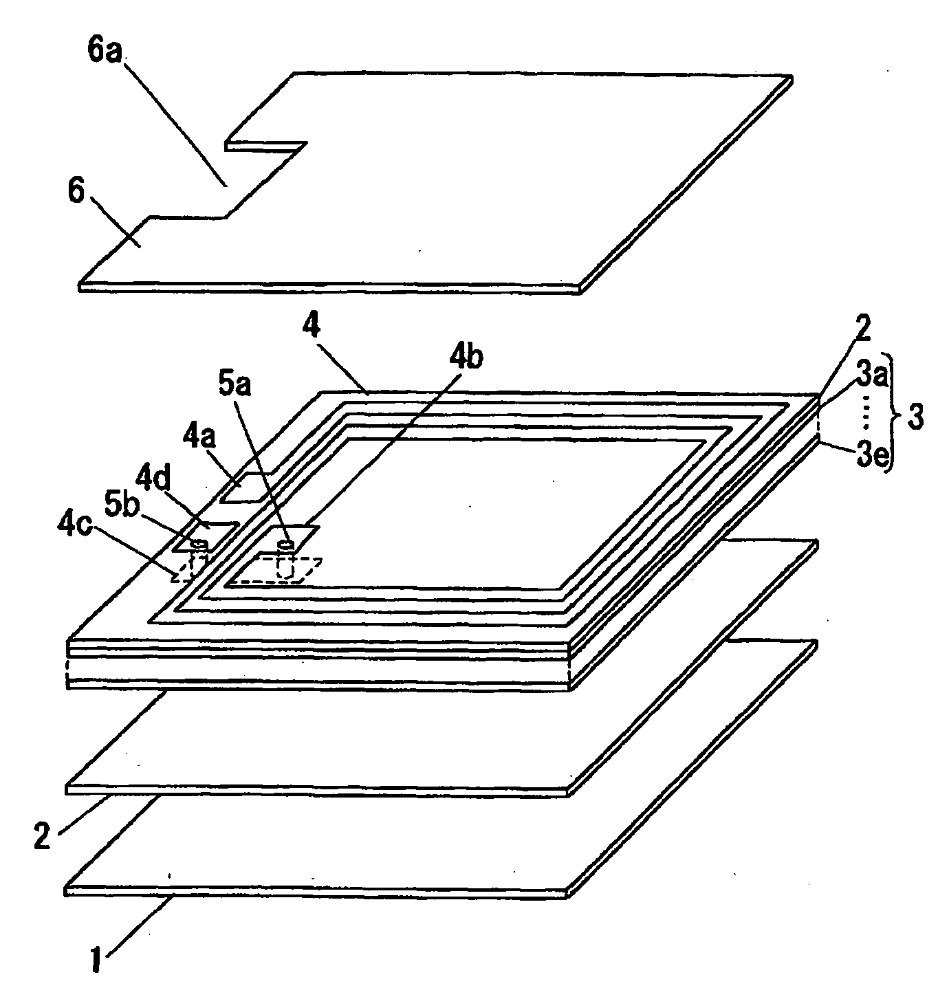
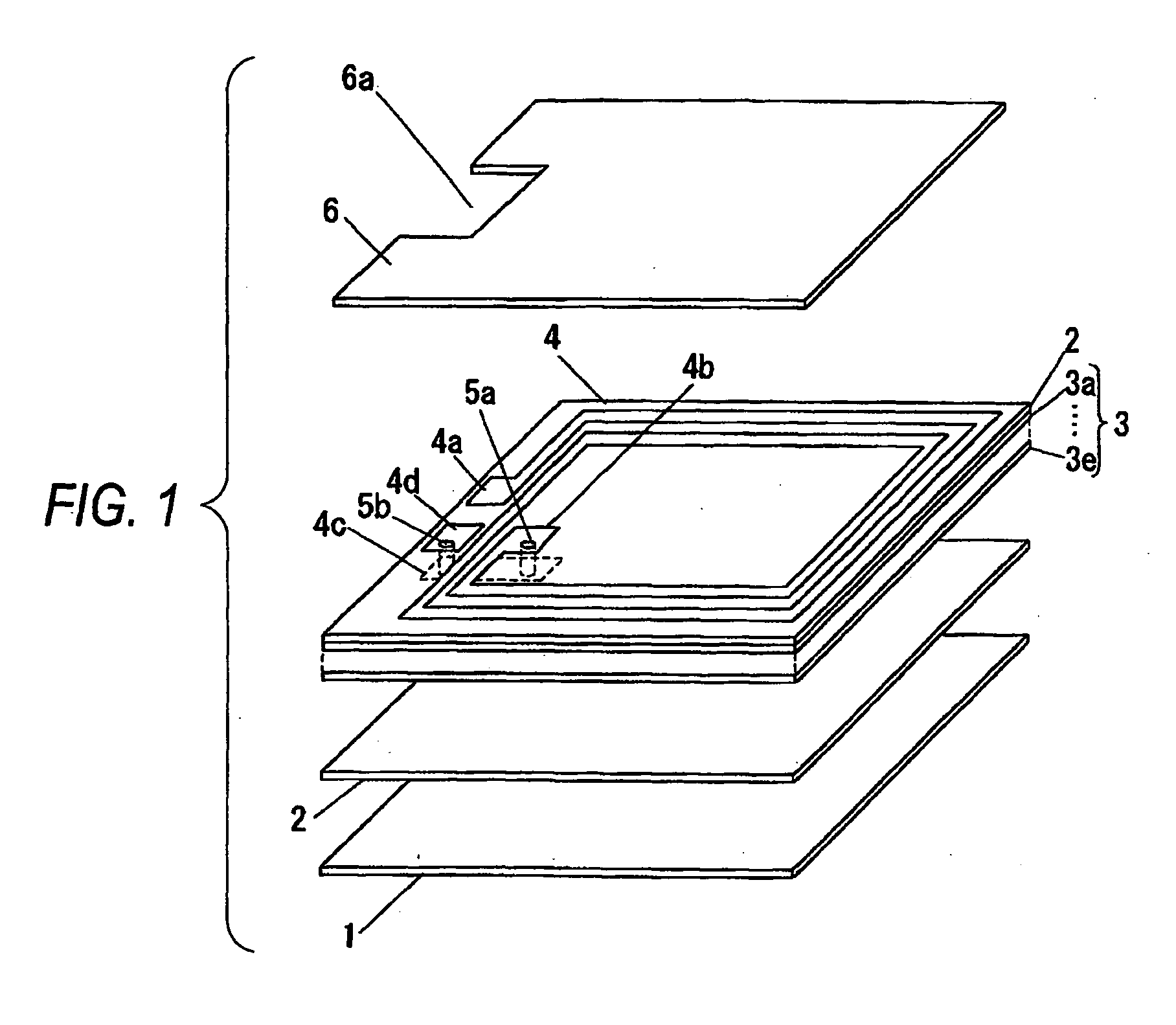
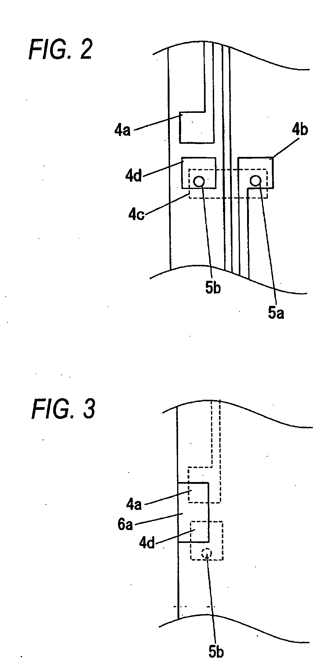
[0032]FIG. 1 is a perspective view of an antenna apparatus according to Embodiment 1 of the invention, FIG. 2 is a plane view of a lead out portion of an antenna end portion in Embodiment 1 of the invention and FIG. 3 is a plane view of a lead out portion of an antenna end portion in Embodiment 1.

[0033]The antenna apparatus...

embodiment 2

[0070]Next, Embodiment 2 of the invention will be explained.

[0071]In Embodiment 2, an explanation will mainly be given of a case of mounting an antenna apparatus to a wireless communication medium processing apparatus starting from a reader or a reader / writer, or a wireless communication medium of an IC card or the like.

[0072]FIG. 4 is a plane view of an antenna apparatus according to Embodiment 2 of the invention, FIG. 5 through FIG. 7 are plane views of portions of the antenna apparatus according to Embodiment 2 of the invention, and FIG. 8 is a constitution view of a wireless communication medium processing apparatus according to Embodiment 2 of the invention. FIG. 9, FIG. 10 are plane views of the antenna apparatus according to Embodiment 2 of the invention. FIG. 11, FIG. 12 are sectional views of the antenna apparatus according to Embodiment 2 of the invention.

[0073]FIG. 4 through FIG. 8 show a case of using two of the antenna apparatus explained in Embodiment 1 and both of the...

embodiment 3

[0097]FIG. 13 is a sectional view of a magnetic sheet structure according to the embodiment of the invention. Numeral 11 designates a magnetic ceramic powder, and numeral 12 designates a film for bonding respective magnetic ceramic powders. First, the magnetic ceramic powder 11 will be explained.

[0098]The magnetic ceramic powder 11 comprises Ni—Zn species ferrite or Mn—Zn species ferrite, Ni—Zn species ferrite is specifically constituted by composition ratios of 48.5 mol % of Fe2O3, 20.55 mol % of ZnO, 20.55 mol % of NiO, and 10.40 mol % of CuO and an average particle size of the magnetic ceramic powder is from 1.5 μm to 2.0 μm.

[0099]Next, the film 12 will be explained. The film 12 is formed on the surface of the magnetic ceramic powder 11 for bonding respectives of the magnetic powders 11. A film 12 is formed by butyral resin and a phthalic acid species plasticizer.

[0100]A green sheet comprising the magnetic member having the above-described constitution is formed as follows.

[0101]...


PUM

PropertyMeasurementUnit
mean particle sizeaaaaaaaaaa
thicknessaaaaaaaaaa

Abstract

An antenna apparatus used in a wireless communication medium or a wireless communication medium processing apparatus constructed by a constitution of including a magnetic member in which a magnetic ceramic powder is used as a major component thereof and which is provided with flexibility, an antenna formed at a surface or inside of the magnetic member, and a matching circuit of the antenna formed at the surface or the inside of the magnetic member.

Description

TECHNICAL FIELD[0001]The present invention relates to an antenna apparatus formed at a magnetic member increasing a magnetic field intensity by forming a closed circuit of a magnetic field in an antenna used in a wireless communication medium processing apparatus for communicating with a wireless communication medium of RF-ID, that is, an IC card, an IC tag or the like, or an antenna mounted on the wireless communication medium per se or the like.BACKGROUND ART[0002]In a background art, an antenna used in a wireless communication processing apparatus for communicating with a wireless communication medium by an electromagnetic induction system, or the wireless communication medium per se is accompanied by a hazard that the antenna is influenced by a metal present at a surrounding thereof, a magnetic field is weakened, mutual inductance necessary for communication becomes insufficient, a communication distance is shortened or communication cannot be carried out. Hence, in order to pre...

Claims


Application Information

Patent Timeline
Patent Type & Authority Applications(United States)
IPC IPC(8): H01Q1/00H01P11/00G06K19/07G06K19/077H01Q1/22H01Q7/00
CPCH01Q1/22Y10T428/24355Y10T29/49016H01Q7/00Y10T428/31612Y10T428/249921
Inventor FUJIMOTO, HIDETSUGUSHIIBA, KONGOSAKITA, HIROMINISHIMURA, KOUJIWATANABE, KOUICHIYANO, HATSUHIROTAKAYAMA, YOSHINIKOMIZOGUCHI, YOSHITAKA
Owner PANASONIC CORP
Why Eureka
Try Eureka