Optical adjusting member, and illumination device and liquid crystal display device including the same

a technology of illumination device and liquid crystal display device, which is applied in the direction of optics, static indicating device, instruments, etc., can solve the problems of affecting the optical effect of the prism sheet, easy damage to the surface, and easy physical damage to the top edge parts of the prism, etc., and achieve the effect of suppressing damag

Inactive Publication Date: 2008-12-11
HITACHT MAXELL LTD
View PDF0 Cites 39 Cited by
  • Summary
  • Abstract
  • Description
  • Claims
  • Application Information

AI Technical Summary

Benefits of technology

[0013]It is an object of the invention to provide an optical adjusting member capable of suppressing damages at the top edge of an optical member.
[0014]Another object of the invention is to provide an optical adjusting member that allows a diffusion effect sufficient for suppressing moiré to be obtained and the light collecting characteristic of incident light to be further improved.
[0016]In the optical adjusting member according to the invention, at least the top edge parts of the lenses are buried in the light diffusion layer. Therefore, the lens surface (the surface of the optical member) is less susceptible to damages. The optical adjusting member according to the invention has a light collecting function by the lenses and a diffusion function by the light diffusion layer.
[0018]In this way, the plurality of bubbles have a small refractive index, and therefore the refractive index of the light diffusion layer can be smaller than that in the case without such bubbles. Therefore, the refractive index difference between the lenses and the light diffusion layer can be increased, so that light can be more refracted at an interface between the lenses and the light diffusion layer. Therefore, the light collecting effect is improved.
[0020]In this case, the first bubbles transmit incident light and do not scatter it. The first bubbles contribute to a reduction in the refractive index of the light diffusion layer and to the light collecting effect. On the other hand, the second bubbles scatter incident light and therefore contribute to the light collecting and diffusion effects. The presence of the first and second bubbles allows the optical adjusting member to have effective light collecting and diffusion functions instead of an excessive diffusion function.
[0025]In this way, light incident on the optical adjusting member is first refracted at an interface between the lens surface and the gap. At the time, the incident light is refracted at the interface between the lens surface and the gap having sufficiently large difference in the refractive index, and therefore a sufficient refraction effect (light collecting effect) is obtained. Then, the light refracted at the interface between the lens surface and the gap is incident on the light diffusion layer and diffused. In this way, the optical adjusting member has light collecting and diffusion effects.

Problems solved by technology

In the conventional prism sheet, the top edge parts of the prism are susceptible to physical damages when it contacts other optical members and the surface is easily damaged.
Once the surface of the prism is damaged, the picture screen of the liquid crystal display panel has for example unwanted light spots, which is likely to impair the optical effect of the prism sheet.
In the optical diffusion sheet disclosed by Japanese Patent No. 3431415, however, the materials to be used for the optical member, the surface adjusting layer and the beads in practice are limited, and more specifically, materials having close refractive indexes are used.
Therefore, the difference in the refractive index between the optical member, the surface adjusting layer and the beads cannot be sufficiently large, so that the effect of refracting incident light by the optical sheet is reduced and a sufficient light collecting characteristic is unlikely to result.
Therefore, the refraction effect between the optical adjusting layer, the optical member, and the beads is small, so that neither a sufficient light collecting characteristic nor diffusion characteristic is obtained.
Note that in order to solve the problem, a material called “high refractive index material” has been developed, but the material is generally expensive.
Therefore, moiré caused by the prism cannot be suppressed.
Furthermore, the top of the prism is not protected and is more easily damaged.

Method used


Image

  • Optical adjusting member, and illumination device and liquid crystal display device including the same
  • Optical adjusting member, and illumination device and liquid crystal display device including the same
  • Optical adjusting member, and illumination device and liquid crystal display device including the same

Examples


first embodiment

[0056]Optical Adjusting Sheet

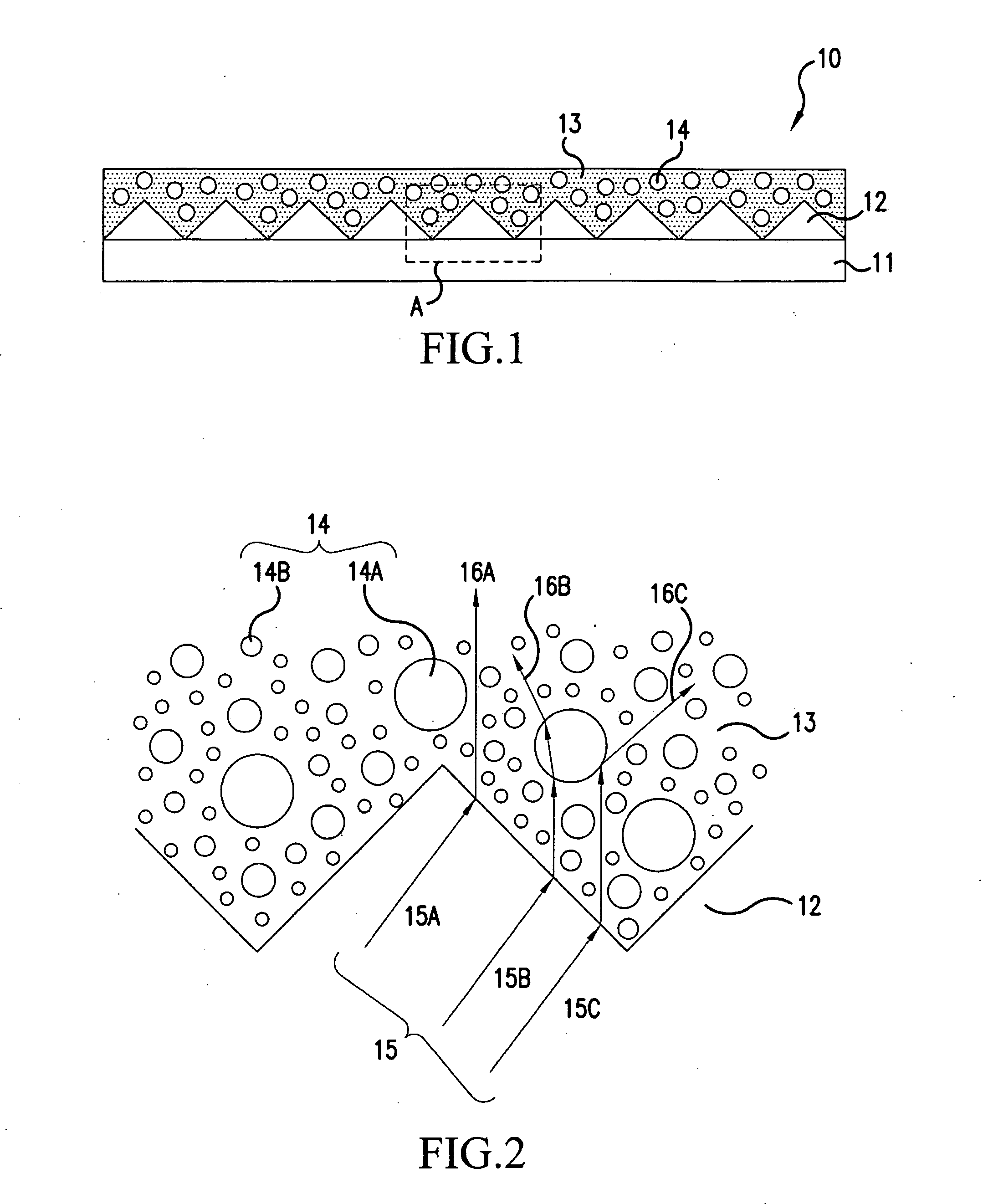
[0057]FIG. 1 is a schematic sectional view of an optical adjusting sheet as an optical adjusting member according to a first embodiment of the invention. With reference to FIG. 1, the optical adjusting sheet 10 includes a sheet type base member 11, a plurality of prisms 12 provided on the base member 11 and a light diffusion layer 13 formed on the plurality of prisms 12.

[0058]The base member 11 has optical transparency. An example of the material of the base member 11 may include resin such as polyethylene terephthalate (PET), polyethylene naphthalate, polystyrene, polycarbonate (PC), polyolefin, polypropylene, and cellulose acetate, and an inorganic transparent material such as glass. An arbitrary shape may be employed for the base member 11, and it may be a sheet type or a plate type having a thickness about in the range from 1 mm to 100 mm. Note that when the sheet type base member 11 is used, the base member 11 preferably has a thickness in the range...

##ventive example 1

Inventive Example 1

[0088]An example of the optical adjusting sheet 10 was prepared. Hereinafter, the optical adjusting sheet will be referred to as “optical adjusting sheet in Inventive Example 1.” The base member was a polyethylene terephthalate (PET) sheet having a refractive index of 1.57 and a thickness of 50 μm. The prisms were made of ultraviolet curing resin with a refractive index of 1.59. As for the size of a section thereof, the vertical angle was 90°, the base had a length of 50 μm, the height was 25 μm, and the pitch was 50 μm. The light diffusion layer was made of aromatic acrylate resin having a refractive index of 1.56 and a plurality of bubbles having sizes from 0.05 μm to 5.0 μm. The total volume ratio of the bubbles relative to the light diffusion layer was 70%. The refractive index of the light diffusion layer was 1.17 in the optical adjusting sheet in Inventive Example 1, and the effective refractive index difference between the light diffusion layer and the pris...

second embodiment

[0090]In the first embodiment, the plurality of bubbles were dispersed in the light diffusion layer, a plurality of hollow particles may be used instead of the plurality of bubbles. When hollow particles are used, after the inner diameter and dispersion ratio thereof are selected in advance, and the particles are be dispersed, the light diffusion layer can be formed. Therefore, the light diffusion effect of the light diffusion layer and the light collecting effect as the optical adjusting sheet may previously be designed, so that control according to the design may readily be achieved, which is preferable in terms of manufacture.

[0091]Now, an optical adjusting sheet according to a second embodiment of the invention will be described.

[0092]Optical Adjusting Sheet

[0093]FIG. 5A is a schematic sectional view of an optical adjusting sheet according to the second embodiment and FIG. 5B is a schematic sectional view of hollow beads.

[0094]As shown in FIG. 5A, an optical adjusting sheet 20 i...


PUM


Abstract

An optical adjusting member according to the invention includes a base member, a plurality of lenses, and a light diffusion layer. The base member has optical transparency. The plurality of lenses are formed on the base member. The light diffusion layer is formed on the plurality of lenses, and at least top edge parts of the lenses are buried in the light diffusion layer. In the optical adjusting member according to the invention, at least the top edge parts of the plurality of lenses are buried in the light diffusion layer and therefore the lenses are less susceptible to damages. The optical adjusting member according to the invention has a light collecting function by the lenses and a diffusion function by the light diffusion layer.

Description

BACKGROUND OF THE INVENTION[0001]1. Field of the Invention[0002]The present invention relates to an optical adjusting member, an illumination device and a liquid crystal display device including the same, and a method of manufacturing an optical adjusting member.[0003]2. Description of the Background Art[0004]Conventional illumination devices such as a backlight unit for a liquid crystal display each include a mechanism for adjusting the diffusion and brightness of light from a light source. Most illumination devices include an optical adjusting member used to control the directivity of light. The optical adjusting member has optical transparency and is capable of collimating incident light in a predetermined direction or diffusing incident light.[0005]A prism sheet is a typical example of the optical adjusting member capable of collimating incident light in a predetermined direction, i.e., capable of controlling its optical directivity (see for example JP 09-133919 A). In general, ...

Claims


Application Information

Patent Timeline
Patent Type & Authority Applications(United States)
IPC IPC(8): G09G3/36
CPCG02B3/0056G02B5/0231G02B5/0247G02B5/0278G02F1/133606G02F2001/133607G02F1/133607
Inventor INOUE, KAZUKOSHIMAZAKI, KATSUSUKEKOYAMA, EIJI
Owner HITACHT MAXELL LTD
Why Eureka
Try Eureka