Display Device with Touch Panel

a display device and touch panel technology, applied in the field of display devices with touch panels, can solve the problems of inability to perform detection, inability to obtain a small gap, inability to retain desired detection accuracy, etc., to suppress ambient light reflection, suppress erroneous recognition of touch panels, and high accuracy

Inactive Publication Date: 2008-12-11
PANASONIC LIQUID CRYSTAL DISPLAY CO LTD +1
View PDF4 Cites 73 Cited by
  • Summary
  • Abstract
  • Description
  • Claims
  • Application Information

AI Technical Summary

Benefits of technology

[0028]Note that the present invention has been made because, in recent years, (1) the advancement of a cold rolling process technique for a metal material allows a metal foil to have a thickness of 5 to 10 μm, (2) the advancement of a fancy plywood technique allows the metal foil having the thickness of 5 to 10 μm to be bonded to a PET film or the like with high accuracy, and (3) the development of a wet etching technique in which a steep taper angle can be realized by ejecting an etchant at high temperature and high pressure allows the metal foil bonded to the PET film to realize a taper angle of almost 90°. Those techniques can realize such a vertical / horizontal dimension that allows the use as a touch panel.
[0029]Further, the one of substrates may be provided with a polarizing plate on an outside thereof. This can suppress ambient light reflection.
[0030]Further, the spacers may be provided in the gap. This allows the gap to be kept uniform. Further, a maximum width of a plan shape of the spacer viewed from a substrate thickness direction may be made larger than the pitch of the metal wiring. This can prevent a short circuit due to deformation of the resin film substrate from developing between the opposing metal wirings, thereby making it possible to suppress erroneous recognition of the touch panel.
[0031]Further, a maximum width of a plan shape of the spacer viewed from a substrate thickness direction may be made larger than the pitch of the metal wiring. This can reduce the fear of the short circuit.
[0032]Further, the width of the metal wiring may be set to less than 50% of the wiring pitch of the metal wiring. Unlike ITO, the metal wiring does not transmit light, resulting in reduction in transmittance, but the setting can prevent the reduction. Further, the wiring width may be set to 13 to 20 μm. This allows the use of an inexpensive emulsion photomask.
[0033]Further, the pitch of the metal wiring and a vertical or horizontal pitch of the display panel may be set to have a relationship of Table 1. This can suppress occurrence of moire.

Problems solved by technology

However, since the transparent electrode having a small line width is high in resistance, a desired detection accuracy cannot be retained.
In addition, since there is the need to consider a taper due to etching in a case where the transparent electrodes are formed to be thick, it is impossible to obtain a small gap.
However, there arise the following problems.
A: Since this drive principle is obtained by applying a high resistance characteristic due to the transparent electrode being a metallic oxide, in a case of using a low resistance film, a voltage drop is reduced, to thereby make it impossible to perform the detection.

Method used


Image

  • Display Device with Touch Panel
  • Display Device with Touch Panel
  • Display Device with Touch Panel

Examples


Embodiment Construction

[0049]Hereinafter, description will be made of an embodiment of the present invention.

[Wiring Layout Mode 1]

[0050]Shown as FIG. 1 is a plan schematic diagram of a touch panel according to this embodiment.

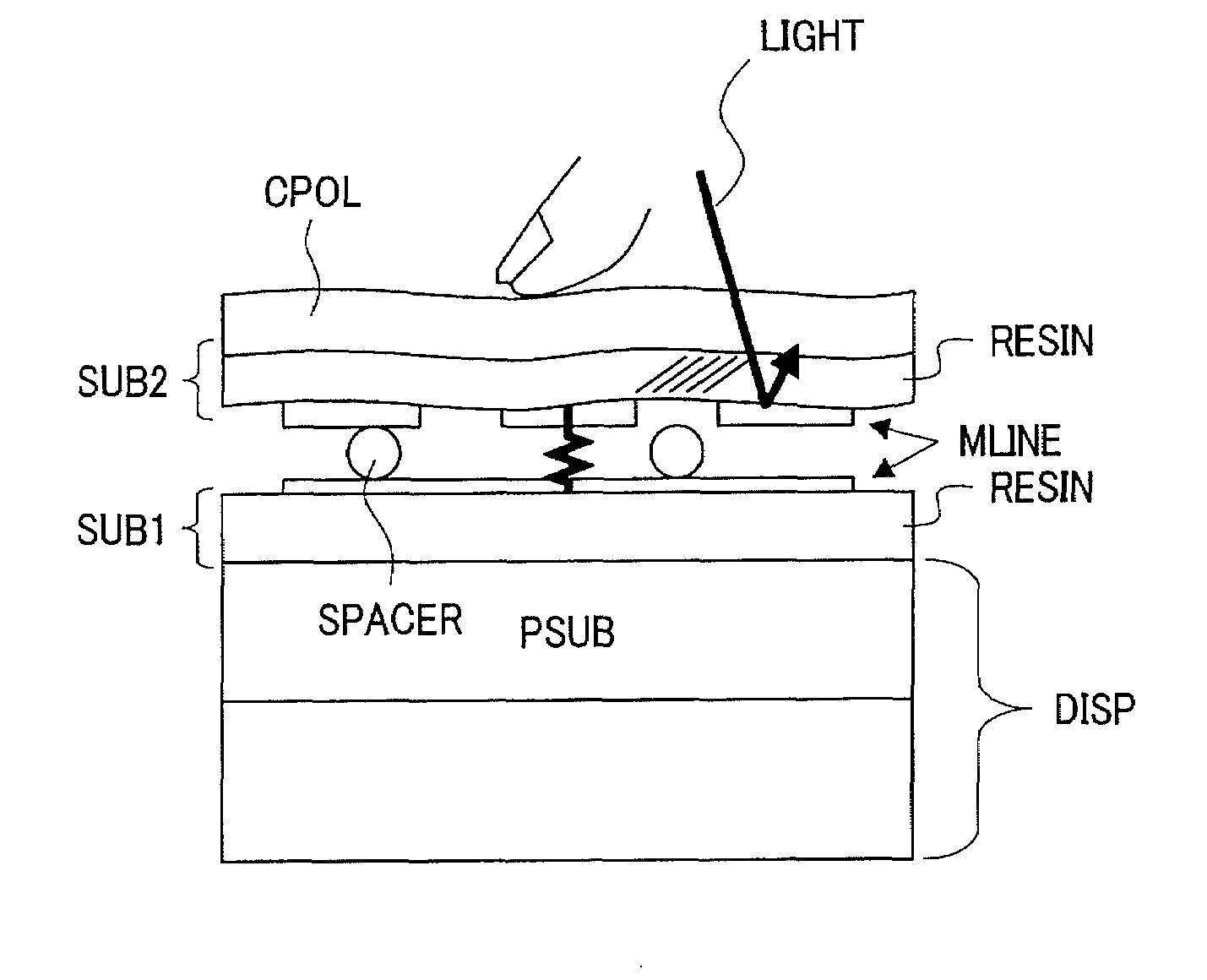
[0051]The touch panel according to this embodiment includes a first substrate SUB1 and a second substrate SUB2 that are resin films formed of PET, a first peripheral circuit SC1, a second peripheral circuit SC2, a power supply, and a detection signal output terminal.

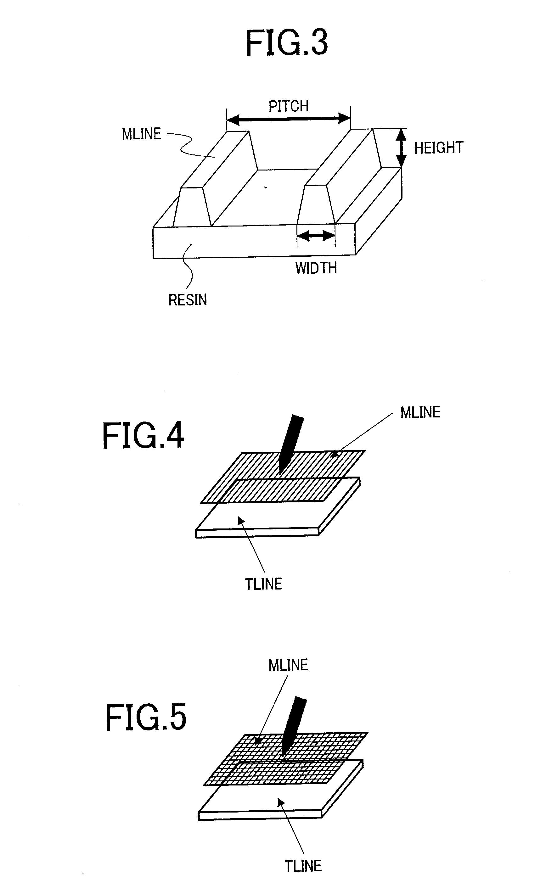
[0052]The first substrate SUB1 and the second substrate SUB2 are flexible wiring substrates formed as follows. That is, a PET film and a copper foil having a film thickness reduced to 10 μm or less by cold rolling process are bonded to each other by using a fancy plywood technique. After that, by using an etching technique in which an etchant is ejected at high temperature and high pressure, the metal is processed into a stripe-shaped wiring having a taper angle of 80° to 90°. The first substrate SUB1 and the second subs...


PUM


Abstract

Suggested is a display device with a touch panel which adopts a novel detection structure. The display device with the touch panel includes: a touch panel including a pair of substrates provided with electrodes on opposing surfaces thereof, and a spacer for retaining a gap between the pair of substrates; and a display panel located on a back surface of the touch panel, in which one of the pair of substrates is provided with a metal wiring formed on a resin.

Description

CROSS-REFERENCE TO RELATED APPLICATION[0001]The present application claims priority from Japanese application JP2007-149884 filed on Jun. 6, 2007, the content of which is hereby incorporated by reference into this application.BACKGROUND OF THE INVENTION[0002]1. Field of the Invention[0003]The present invention relates to a display device with a touch panel, in particular, a coordinate detection structure of a touch panel.[0004]2. Description of the Related Art[0005]Major systems adopted by conventional touch panels include a system of detecting an optical change and a system of detecting a change in electric characteristic. Of those, the system of detecting an optical change presents a problem of instability in detection accuracy.[0006]The system of detecting a change in electric characteristic is conventionally divided into a resistive film system and a capacity system.[0007]FIG. 13 shows a conventional touch panel of a capacity system. The touch panel includes a transparent electr...

Claims


Application Information

Patent Timeline
Patent Type & Authority Applications(United States)
IPC IPC(8): G06F3/041
CPCG06F3/0412
Inventor MATSUDATE, NORIHARUOOKAWARA, TAKESHINAKAMURA, NORIHIRO
Owner PANASONIC LIQUID CRYSTAL DISPLAY CO LTD
Why Eureka
Try Eureka