Plasma shunting apparatus and method for ring laser gyroscope

a gyroscope and laser shunting technology, applied in the field of ring lasers, can solve the problems of reducing the laser intensity in the cavity, reducing the cost of fabricating and installing mirror shields, and reducing so as to reduce the exposure of ring laser mirrors, and reduce the cost of installation

Active Publication Date: 2008-12-11
LITTON SYST INC
View PDF6 Cites 8 Cited by
  • Summary
  • Abstract
  • Description
  • Claims
  • Application Information

AI Technical Summary

Benefits of technology

[0005]The present invention provides an inexpensive, easy to install plasma shunt that reduces exposure of ring laser mirrors to contaminants carried by the laser gain medium.

Problems solved by technology

This devitrified frame material slowly degrades the mirrors and reduces the laser intensity in the cavity.
Mirror shielding can be effective, but presently known mirror shields are costly to fabricate and install.

Method used


Image

  • Plasma shunting apparatus and method for ring laser gyroscope
  • Plasma shunting apparatus and method for ring laser gyroscope
  • Plasma shunting apparatus and method for ring laser gyroscope

Examples


Embodiment Construction

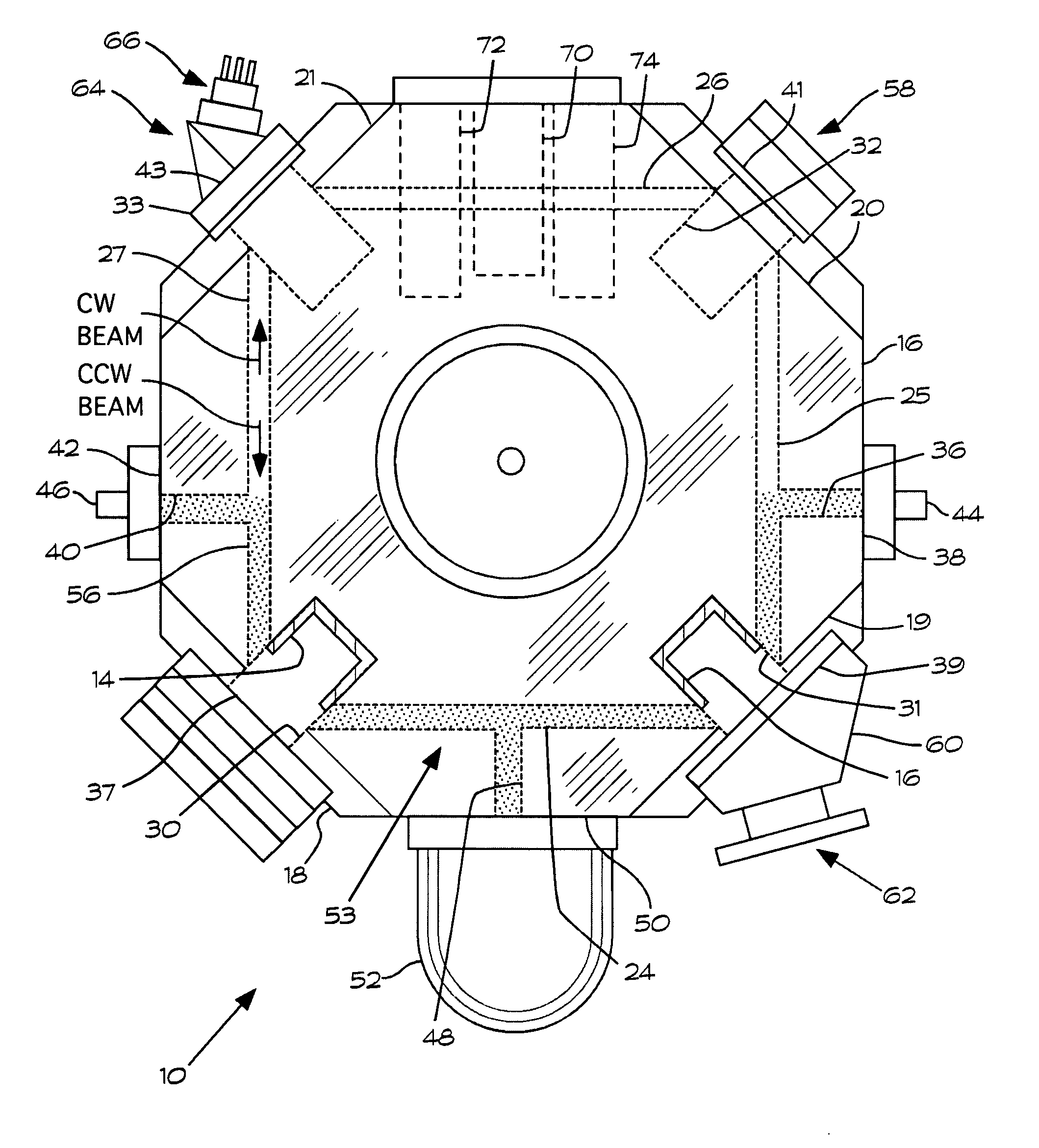
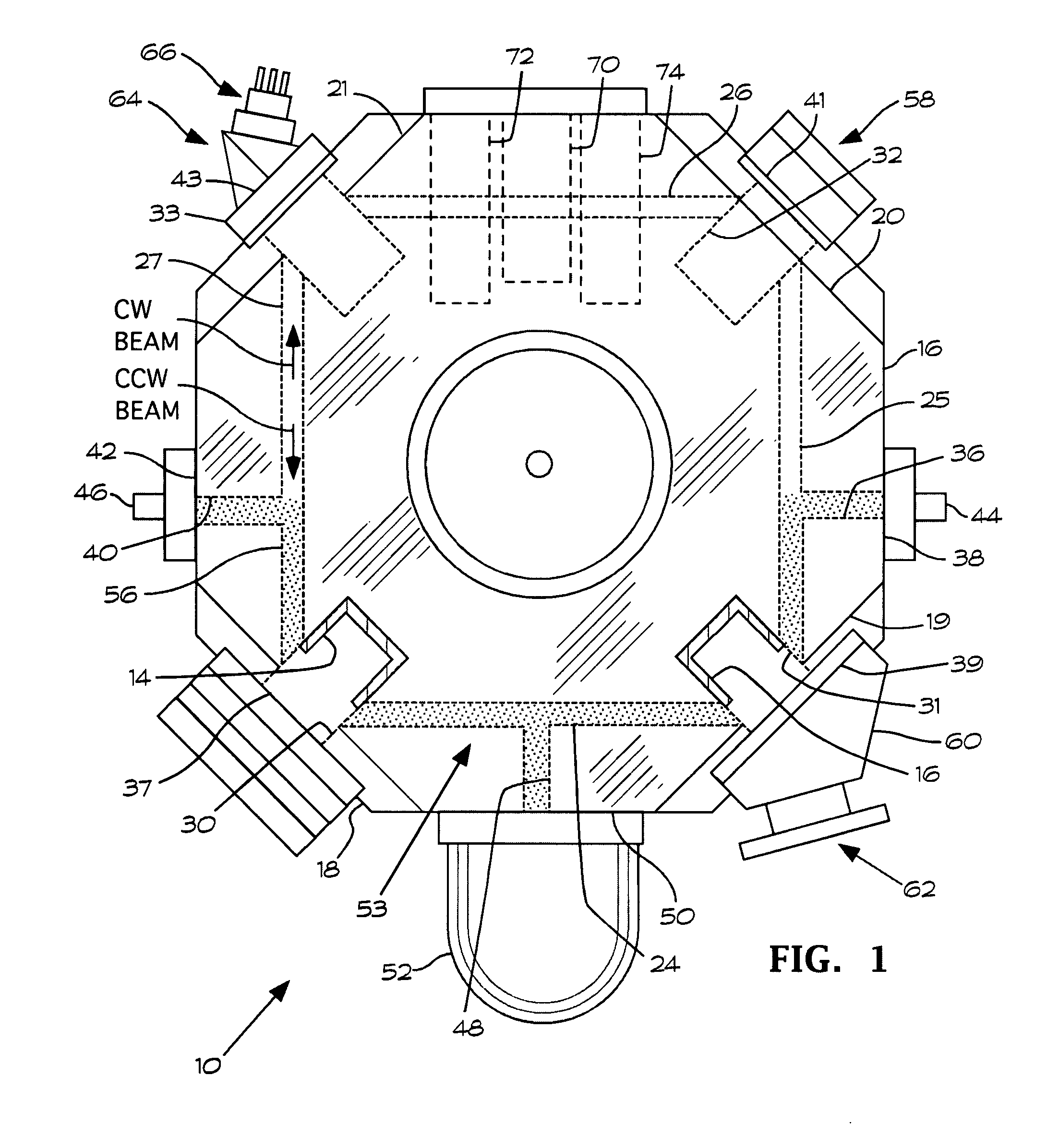
[0014]FIG. 1 illustrates basic structural features of a zero lock ring laser gyroscope 10 that includes plasma shunts 12 and 14 according to the present invention. The basic features are of such ring laser gyroscopes are well-known and therefore are explained only briefly herein to facilitate an understanding and appreciation of the present invention.

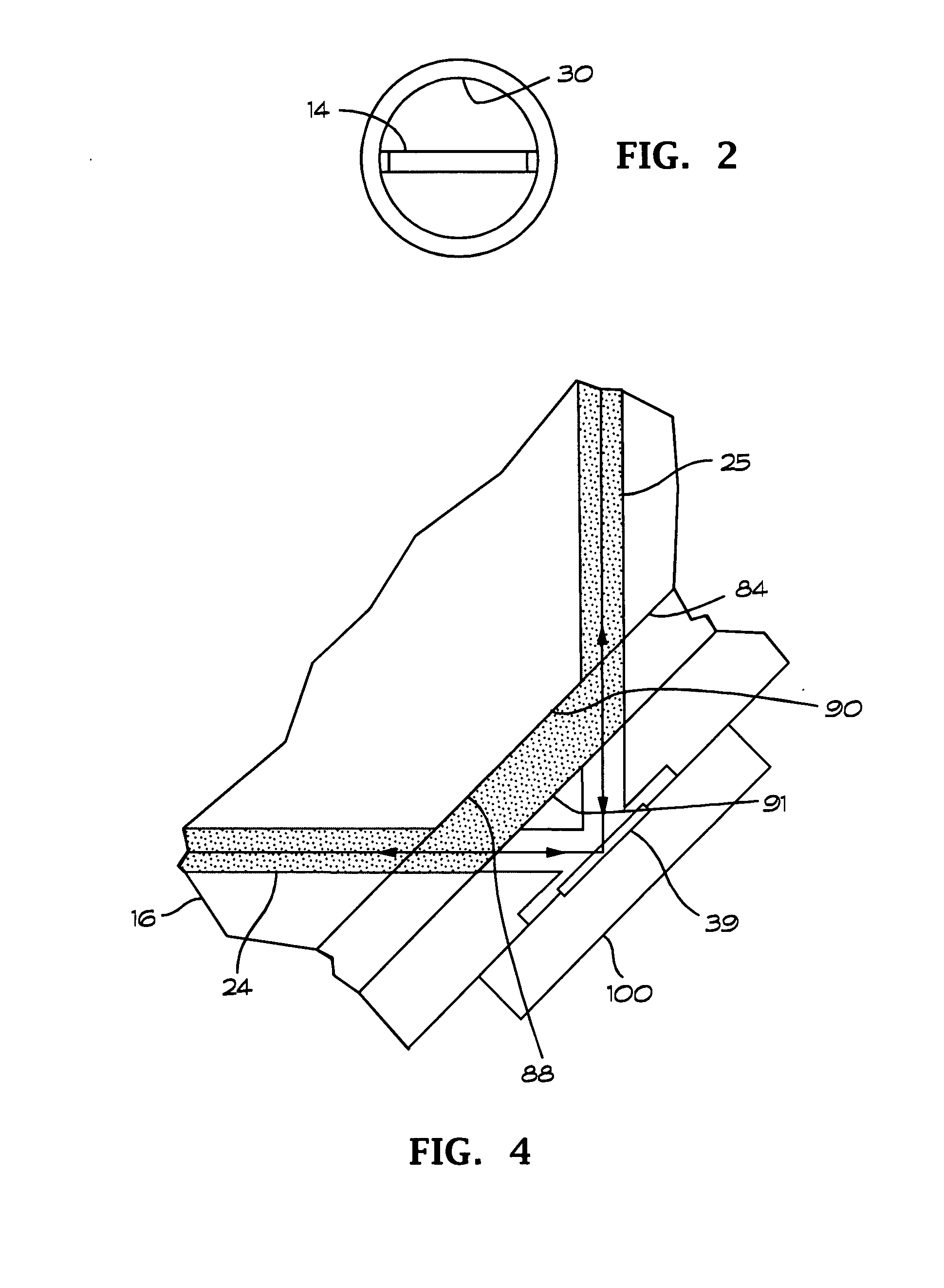
[0015]The ring laser gyroscope includes a frame 16 that preferably is formed of a glass-ceramic composite material that has a very low coefficient of thermal expansion. The frame 16 includes four exterior planar surfaces 18-21. Circular bores 24-27 formed in the frame 16 between adjacent pairs of the mirrors 18-21 form a continuous cavity 28. In the embodiment shown in FIG. 1 mirror wells 30-33 are formed in the frame 16 at the planar surfaces 18-21, respectively. Mirrors 37, 39, 41 and 43 are mounted to the frame 16 over the outer ends of the mirror wells 30, 31, 32 and 33, respectively.

[0016]A first anode bore 36 formed in the frame 1...


PUM


Abstract

A ring laser gyroscope includes a first plasma shunt arranged to prevent the plasma from contacting a first mirror in the gain region and a second plasma shunt arranged to prevent the plasma from contacting a second mirror in the gain region. The first and second plasma shunts may comprise electrical conductors located in the respective mirror wells and arranged such that contact between the plasma and the electrical conductors quenches the plasma in the mirror wells and produces electrical currents that travels across the mirror wells. The electrical conductors may be formed as metallized strips arranged to extend across the mirror wells, or they may be formed from metal wires. The plasma shunts may alternatively comprise diversion passages formed in the frame and arranged such that the plasma fills the diversion passages and bypasses the mirrors.

Description

BACKGROUND OF THE INVENTION[0001]This invention relates generally to ring lasers and particularly to ring laser gyroscope rotation sensors. Still more particularly, this invention relates to apparatus and methods for preventing plasma in the lasing medium of a ring laser gyroscope from impinging on mirrors used to direct the laser beam in a closed path.[0002]Ring laser gyroscopes have been used in navigation systems for several years. A plurality of mirrors directs counterpropagating laser beams through a closed optical path defined by a plurality of passages or bores in a frame that is typically formed of a thermally stable glass / ceramic material. The laser beam is formed by applying a suitable voltage to a gain medium such as a mixture of Helium and Neon to produce a plasma. Electrons in the plasma emit light as they transition from a high energy state to a lower energy state. The optical path is formed to have a selected length so that a selected frequency of light produced in th...

Claims


Application Information

Patent Timeline
Patent Type & Authority Applications(United States)
IPC IPC(8): G01C1/10B60R1/00
CPCG01C19/665H01S3/0346H01S3/038H01S3/0835H01S3/2222
Inventor MITCHELL, ROBERTSAMMON, SHANEBATHELT, JR., CARL
Owner LITTON SYST INC
Why Eureka
Try Eureka