
Wind Power Generation System and Control Method Thereof

Active Publication Date: 2008-12-11
HITACHI IND PROD LTD
View PDF9 Cites 30 Cited by
  • Summary
  • Abstract
  • Description
  • Claims
  • Application Information

AI Technical Summary

Benefits of technology

The present invention aims to prevent the capacitor in a wind power generation system's excitation power converter from being overcharged to an excessively high voltage by overcurrent caused by power system failure or disturbance. The invention achieves this by connecting an overcurrent consuming unit to the DC part of the converter. This prevents the capacitor from being overcharged and allows for quick restart of the operation without the need for disconnecting the system connection point after recovery of the power system.

Problems solved by technology

In this case, excessive current is induced in the rotor winding, causing excessive current passing through the excitation converter connected to the rotor-side of the generator.

Method used


Image

  • Wind Power Generation System and Control Method Thereof
  • Wind Power Generation System and Control Method Thereof
  • Wind Power Generation System and Control Method Thereof

Examples


embodiment 1

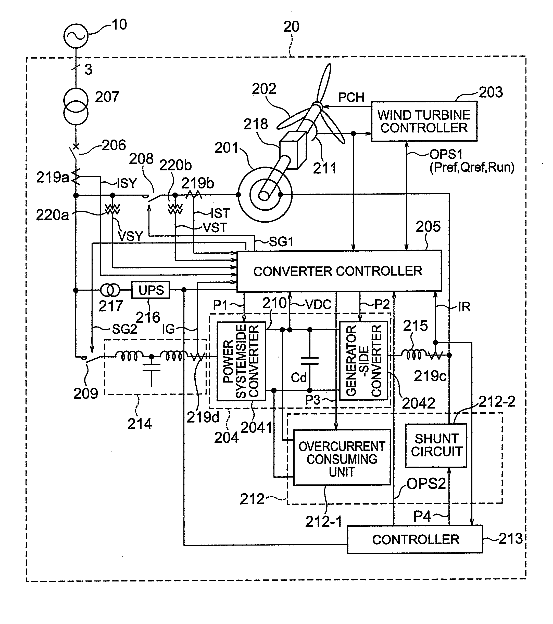
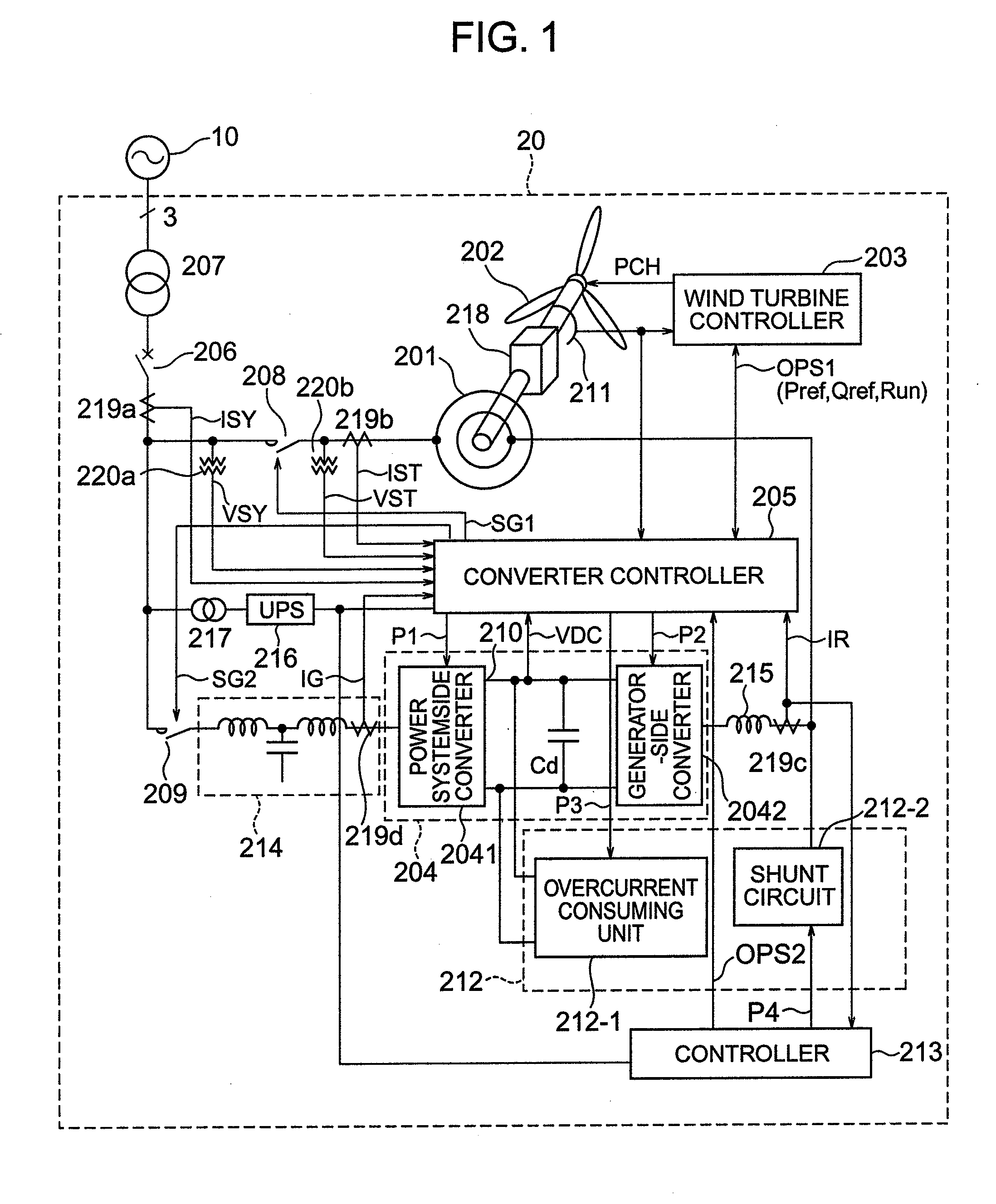
[0028]FIG. 1 is a schematic circuit diagram (single-line wiring diagram) showing the circuit configuration of a wind power generation apparatus 20 in accordance with a first embodiment of the present invention.

[0029]The wind power generation apparatus 20 is connected to a power system 10 via power lines. The wind power generation apparatus 20 is mainly composed of a generator 201, blades 202, a wind turbine controller 203, a converter (excitation apparatus) 204, a converter controller 205, a system failure countermeasure unit 212 and a system failure countermeasure unit controller 213.

[0030]The blades 202 are mechanically connected to the rotor of the generator 201 (via gears 218 or the like). The rotor winding of the generator 201 is electrically connected to the converter 204. The stator of the generator 201 is electrically connected to the power system 10 via a circuit breaker 206, a coupling transformer 207, etc.

[0031]The wind turbine controller 203 detects wind speed, controls ...

embodiment 2

[0111]FIG. 13 is a schematic circuit diagram showing the circuit configuration of a wind power generation apparatus 20 in accordance with a second embodiment of the present invention, in which power supply to the system failure countermeasure unit controller 213 differs from that in the first embodiment.

[0112]In the second embodiment, the electric power for the system failure countermeasure unit controller 213 is supplied from the DC part 210 of the converter 204. The control power can be obtained from the DC part 210 of the converter 204 since the voltage of the DC part 210 is maintained within a prescribed range by the resistor R2 and the semiconductor switch S71.

[0113]With this configuration, the need of increasing the capacity of the uninterruptible power supply (UPS) 216 for the addition of the system failure countermeasure unit can be eliminated, as well as achieving the same effects as the first embodiment.

embodiment 3

[0114]FIG. 14 is a schematic circuit diagram showing the circuit configuration of a wind power generation apparatus 20 in accordance with a third embodiment of the present invention, in which the sensor input to the system failure countermeasure unit controller 213 differs from that in the first embodiment.

[0115]In the third embodiment, the system failure countermeasure unit controller 213 makes the judgment on the system failure based on overcurrent of the stator current IST. The stator current IST, which becomes excessive in the event of a system failure similarly to the generator-side converter current IR, can also be used for the system failure judgment. Further, in case of a short circuit in a brush part of a rotor winding terminal, the generator-side converter current IR rises more sharply than the stator current IST (since the converter 204 is still in operation) and thereafter the rotor current attenuates when the converter stops. On the other hand, the overcurrent of the st...


PUM


Abstract

In a wind power generation system, an energy consuming unit is connected to a DC part of a generator-side converter. A shunt circuit is connected between the generator-side converter and a rotor of an AC-excited power generator. In the event of system failure, the switching operation of the converter is stopped, the shunt circuit is put into operation, and the energy consuming unit is put into operation so that DC voltage (voltage of the DC part) is maintained within a prescribed range.

Description

CROSS-REFERENCE TO RELATED APPLICATION[0001]The present application relates to subject matters described in a co-pending patent application Ser. No. 11 / 769,753 filed on Jun. 28, 2007 entitled “VARIABLE SPEED WIND POWER GENERATION SYSTEM”, Ser. No. 11 / 751,742 filed on May 22, 2007 entitled “WIND POWER GENERATION APPARATUS, WIND POWER GENERATION SYSTEM AND POWER SYSTEM CONTROL APPARATUS”, Ser. No. 11 / 954,453 filed on Dec. 12, 2007 entitled “WIND POWER GENERATION SYSTEM”, Ser. No. 11 / 116,272 filed on May 7, 2008 entitled “WIND POWER GENERATION SYSTEM AND OPERATING METHOD THEREOF” and serial No. to be filed on May 30, 2008 entitled “WIND POWER GENERATION SYSTEM AND METHOD OF CONTROLLING POWER CONVERTER” every which by Masaya Ichinose, et al. and assigned to the assignees of the present application. The disclosures of these co-pending applications are incorporated herein by reference.BACKGROUND OF THE INVENTION[0002]The present invention relates to a wind power generation apparatus, and ...

Claims


Application Information

Patent Timeline
Patent Type & Authority Applications(United States)
IPC IPC(8): H02H7/06
CPCF03D9/003F05B2270/1071H02J2003/388H02P2101/15Y02E10/72Y02E10/763H02J3/386H02P9/102F03D9/255H02J3/388F03D15/10H02J2300/28H02J3/381Y02E10/76
Inventor ICHINOSE, MASAYAFUTAMI, MOTOOSAKAI, HIROMITSUYAMASHITA, KOJIRO
Owner HITACHI IND PROD LTD
Learn More