

Camera shaking correcting device, and image pickup device
a technology of image pickup and camera shake, which is applied in the field of camera shake correction device and image pickup device, can solve the problems of high computational capacity, long computing time, and poor quality of photographed images, and achieve the effect of suppressing the occurrence of blurring in photographed images and simple computation processing
- Summary
- Abstract
- Description
- Claims
- Application Information
AI Technical Summary
Benefits of technology
Problems solved by technology
Method used
Image

Examples
first embodiment
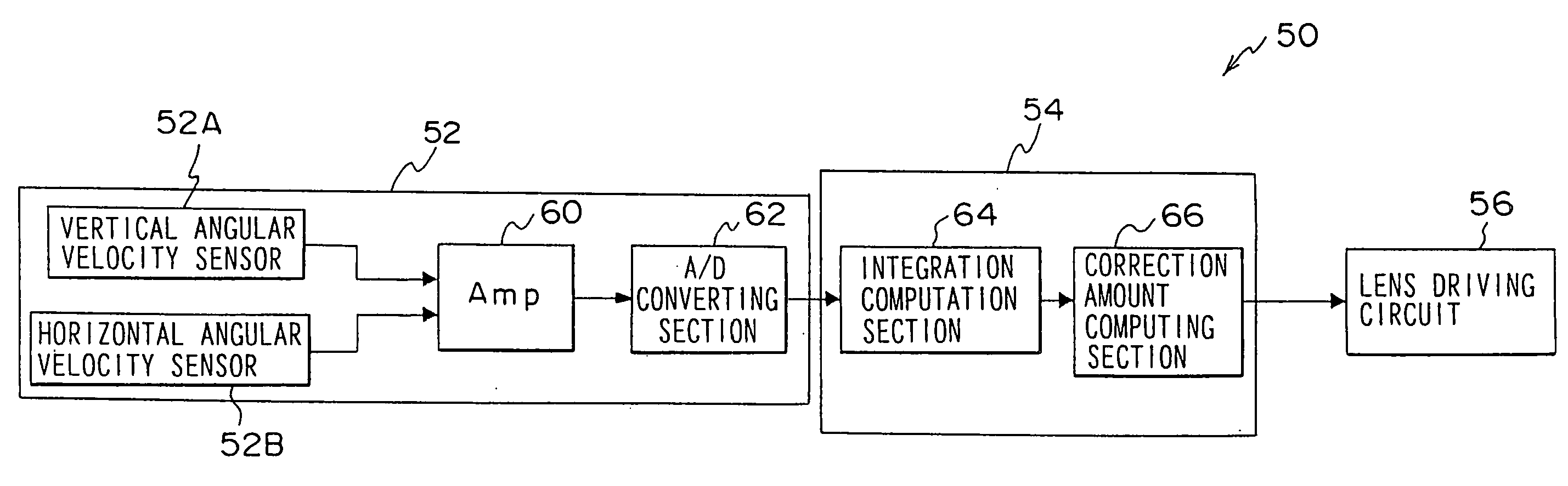
[0092]As shown in FIG. 3, the gyro sensor 52 has a vertical angular velocity sensor 52A and a horizontal angular velocity sensor 52B. The vertical angular velocity sensor 52A and the horizontal angular velocity sensor 52B detect the angular velocity in the vertical direction and the angular velocity in the horizontal direction of the digital camera 10, and output signals corresponding to the detected angular velocities. Note that, instead of the angular velocity sensors, acceleration sensors or angular acceleration sensors or the like may be used.
[0093]The outputs of the gyro sensor 52 are inputted to the correction computing section 54 via an amplifying circuit (Amp) 60 and an A / D converter 62. The correction computing section 54 has a microcomputer (not shown), and an integration computing section 64 (integration processing section) and a correction amount computing section 66 are formed thereby.
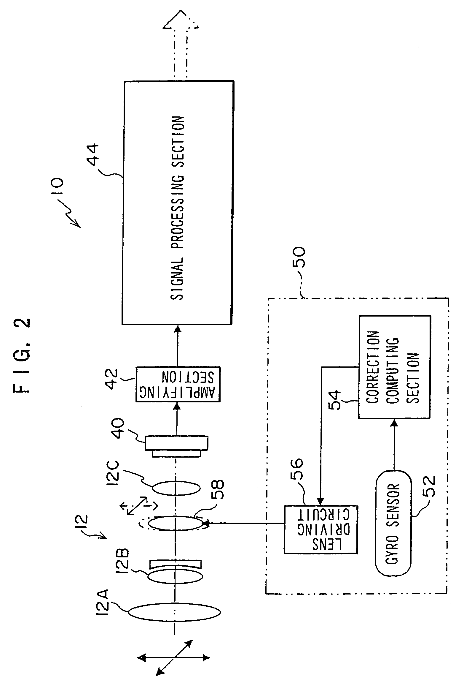
[0094]Due to the lens driving circuit 56 driving an actuator (not illustrated) on the ...
second embodiment
[0128]The schematic structure of main portions of the shaking correcting module 50 relating to a second embodiment are shown in FIG. 7. The gyro sensor 52 has the vertical angular velocity sensor 52A and the horizontal angular velocity sensor 52B. The vertical angular velocity sensor 52A and the horizontal angular velocity sensor 52B detect the angular velocity in the vertical direction and the angular velocity in the horizontal direction of the digital camera 10, and output signals corresponding to the detected angular velocities. Note that, instead of an angular velocity sensor, an acceleration sensor, an angular acceleration sensor, or the like may be used.
[0129]HPFs 60, which damp low-band frequency components from the signals outputted from the vertical angular velocity sensor 52A and the horizontal angular velocity sensor 52B respectively, and amplifier circuits (Amp) 62, which amplify the signals which have passed through the HPFs 60, are provided at the gyro sensor 52. In th...
third embodiment
[0175]A third embodiment of the present invention will be described next. Note that the basic structure of the third embodiment is the same as the above-described second embodiment. In the third embodiment, parts which are the same as in the second embodiment are denoted by the same reference numerals, and description thereof is omitted.
[0176]The schematic structure of a shaking correcting module 50A applied to the third embodiment is shown in FIG. 15.
[0177]In addition to the A / D converter 64, the integration processing section 66, and the control voltage converting section 68 at a correction computing section 54A, the shaking correcting module 50A also has a filter processing section 86 between the integration computing section 66 and the control voltage converting section 68.
[0178]At the filter processing section 86, the drift component contained in the angular velocity signal is removed from the integrated value which is obtained by integrating the angular velocity signal outputt...
PUM
 Abstract
Description
Claims
Application Information