
Method for applying a resist layer, uses of adhesive materials, and adhesive materials and resist layer

a resist layer and adhesive material technology, applied in the field of resist layers, can solve the problems of complex removal of photoresist layer residues after the development, cost-intensive disposal of solvents, etc., and achieve the effects of facilitating the later removal of residual regions, and reducing the adhesive force of residual regions

Inactive Publication Date: 2008-12-11
INFINEON TECH AG
View PDF31 Cites 0 Cited by
  • Summary
  • Abstract
  • Description
  • Claims
  • Application Information

AI Technical Summary

Benefits of technology

This method enables uniform resist layer application, efficient utilization of resist materials, and simplified residue removal, reducing solvent usage and process complexity, while allowing for thicker resist layers and smaller feature sizes in patterning.

Problems solved by technology

Moreover, the removal of residues of the photoresist layer after the development may be complicated.
By way of example, it may be necessary to use a solvent whose disposal is cost intensive.

Method used


Image

  • Method for applying a resist layer, uses of adhesive materials, and adhesive materials and resist layer
  • Method for applying a resist layer, uses of adhesive materials, and adhesive materials and resist layer
  • Method for applying a resist layer, uses of adhesive materials, and adhesive materials and resist layer

Examples


Embodiment Construction

[0034]A method for applying a resist layer to a base layer, selectively irradiated and developed will now be described more fully with reference to the accompanying drawings. In each of the following figures, components, features and integral parts that correspond to one another each have the same reference number. The drawings of the figures are not true to scale.

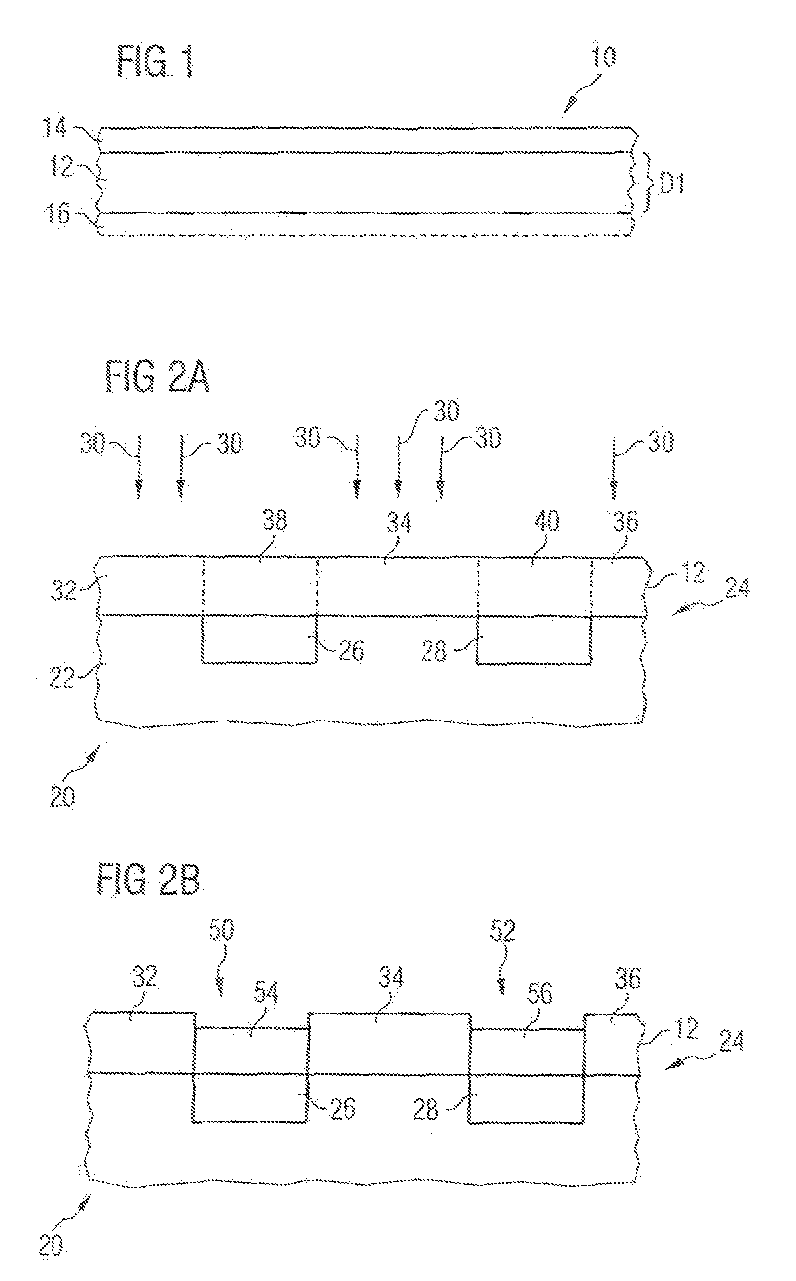
[0035]FIG. 1 shows an adhesive tape 10 having an adhesive layer 12 and an outer layer 14. The adhesive layer 12 includes a substance with an adhesive force that may be reduced by irradiation with ultraviolet light. During the fabrication of the adhesive tape 10, the adhesive force of the adhesive layer 12 on a silicon wafer is 2.0 N / 20 mm, for example. The thickness of the adhesive layer 12 is 50 μm in the exemplary embodiment. One example of the composition of the adhesive layer 12 will be explained in more detail further below.

[0036]The outer layer 14 is composed, for example, of PET or PETP (polyethylene terephthalate),...


PUM

PropertyMeasurementUnit
sizeaaaaaaaaaa
dimensionsaaaaaaaaaa

Abstract

A method in which a resist layer is applied to a base layer is disclosed. The resist layer includes an adhesive material, and the adhesive force of the adhesive material decreases or increases during an irradiation process. Residues of the resist layer may be stripped using the disclosed method.

Description

PRIORITY AND CROSS REFERENCE TO RELATED APPLICATION[0001]This application is a divisional of U.S. Ser. No. 11 / 156,405, which is a continuation of International Application No. PCT / EP2003 / 014460 filed Dec. 18, 2003, which claims priority to German application 102 60 235.2 filed Dec. 20, 2002, both of which are incorporated herein in their entirety by reference.BACKGROUND[0002]1. Field of the Invention[0003]The present invention relates to the field of resist layers, and more particularly, it relates to a method for applying a resist layer to a base layer, selectively irradiated and developed.[0004]2. Description of the Related Art[0005]Methods have been used in the context of a lithography process for patterning a base layer after the development of a resist layer and in the context of a galvanic method in which contact areas are deposited on connecting pads in the base layer. A photoresist that is spun onto the base layer in the liquid state has hitherto been used as the resist laye...

Claims


Application Information

Patent Timeline
Patent Type & Authority Applications(United States)
IPC IPC(8): G03F7/11G03F7/16G03F7/32G03F7/34
CPCG03F7/16G03F7/34G03F7/32G03F7/161
Inventor KRONINGER, WERNERSCHNEEGANS, MANFRED
Owner INFINEON TECH AG
Learn More