Fuel Injection System

Inactive Publication Date: 2008-12-18
VOLVO LASTVAGNAR AB
View PDF3 Cites 15 Cited by
  • Summary
  • Abstract
  • Description
  • Claims
  • Application Information

AI Technical Summary

Benefits of technology

[0014]When injection at a higher rate is required, the pressure in the inlet port is increased further and above the opening pressure of the poppet valve, which then moves downward and opens a large flow area between the poppet and its seat allowing fuel to escape from the poppet pressure chamber out to the combustion chamber, thereby commencing a second stage of the injection During this downward movement of the poppet valve, the outlet control orifice becomes overlapped by the edge of the return channel or groove, closing the flow path from the needle spring chamber to the return port. Further opening of the poppet valve aligns the inlet control orifice with the supply channel so that the fuel under pressure flows into the needle spring chamber and assists the needle return spring in closing the needle valve. Thus the needle valve

Problems solved by technology

However, depletion of reserves and rising cost of crude oil that at the present time remains practically the only source of fuel for diesel engines, initiate efforts aimed at finding alternative fuels suitable for diesel engines.
The difficulties of creating high DME injection pressures, arising from its much poorer lubricity, lower viscosity and greater compressibility, make it necessary to utilize nozzles with very large flow areas to achieve the high flow rates and injected volumes.
This creates certain difficulties for conventional diesel nozzle designs featuring a needle valve controlling flow to spray orifices, arising from too large orifice number and diameter required.
Operation on DME, thanks to low sooting quality of the fuel, is likely to be forgiving to this design's propensity to fuel splashing and fuel film formation on external nozzle surfaces, but the exposure of the guide, which has to be relatively closely matched for effective orific

Method used


Image

  • Fuel Injection System
  • Fuel Injection System
  • Fuel Injection System

Examples


Embodiment Construction

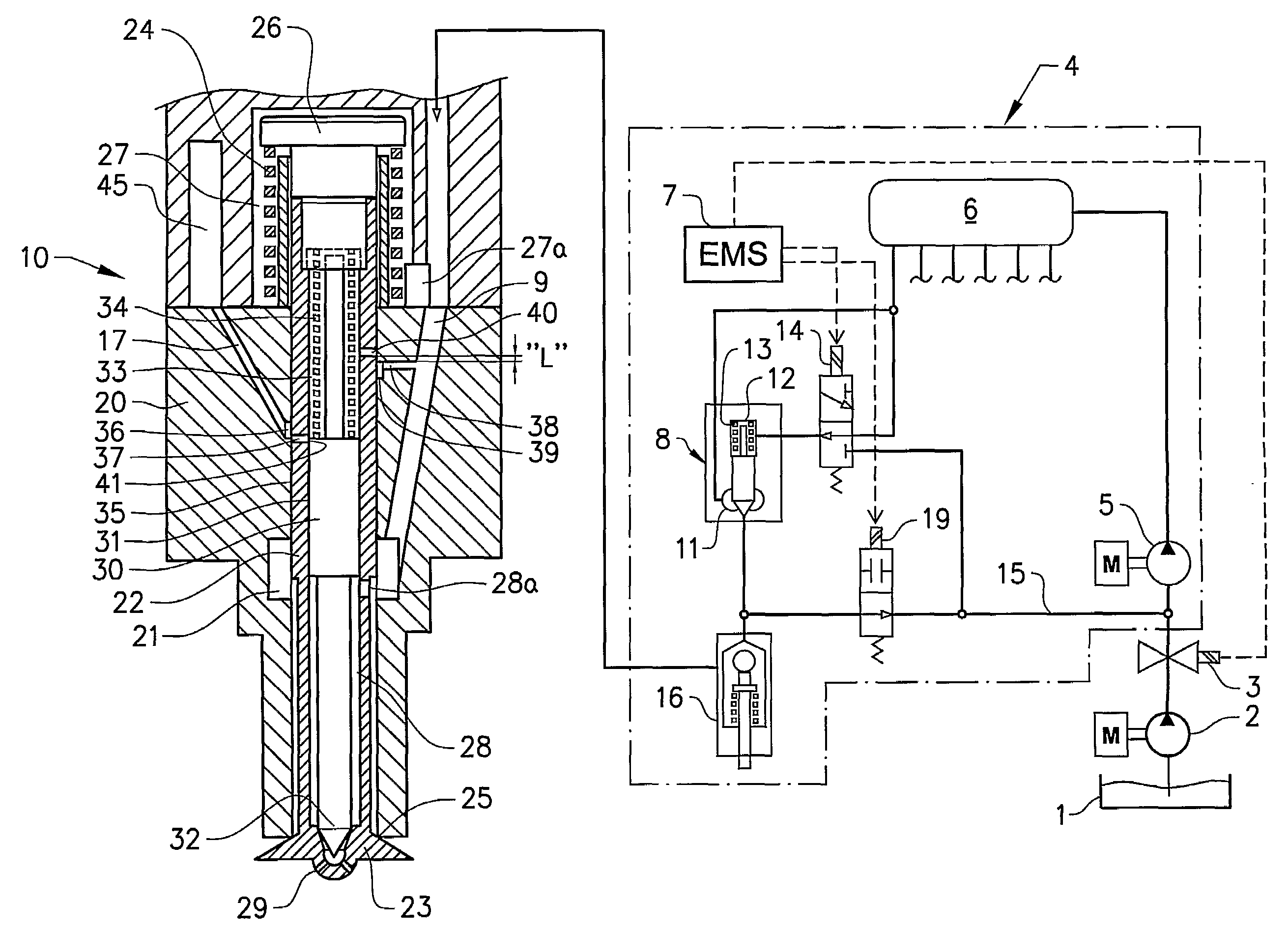
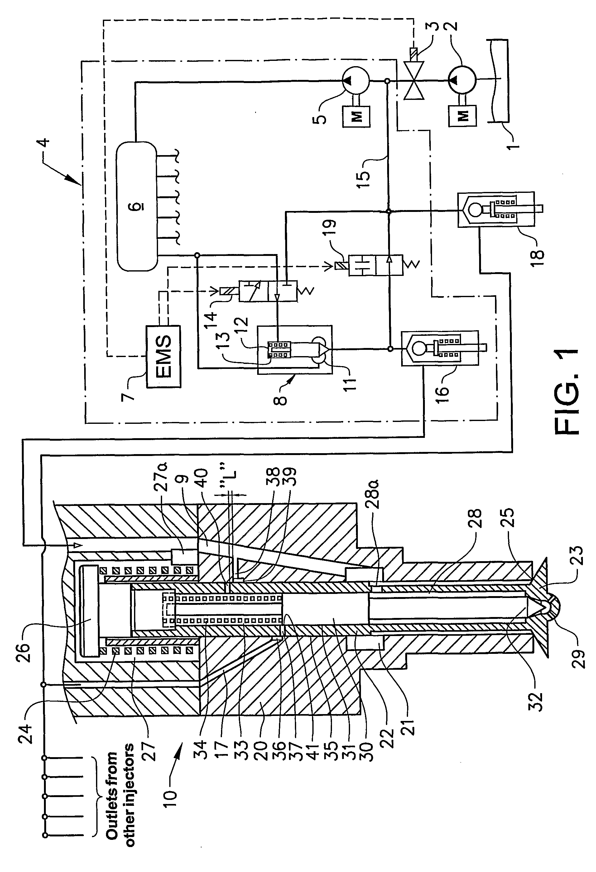
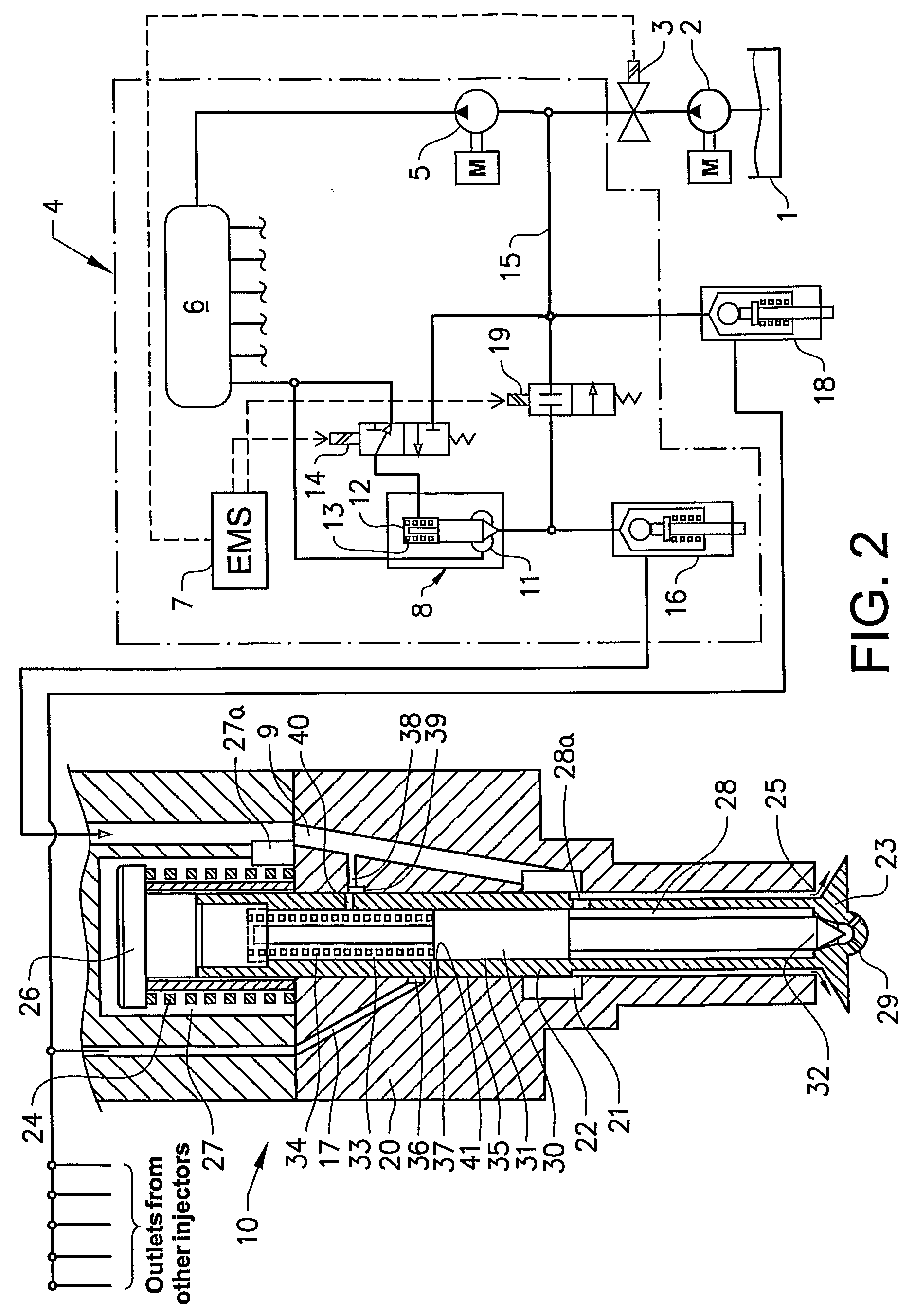
[0021]In the preferred embodiment, the fuel injection system according to present invention contains a fuel tank 1, a feed pump 2 and associated components (not shown), a conventional isolating valve 3, a source of variable pressure 4 comprising a high-pressure pump 5, a common rail 6, to which a plurality of injectors are connected, and an engine management system (EMS) 7. A hydraulically operated valve 8 is connected between the common rail 6 and the inlet 9 of a nozzle 10, the inlet of the hydraulically operated valve 8 being connected to the common rail 6. The hydraulically operated valve preferably has a precision-matched stem and forms an outlet chamber 11 and a control chamber 12, and is preferably biased towards its closed position by a resilient means 13. The control chamber 12 of the valve 8 can be connected by a three-way pilot valve 14 to either the common rail 6 or a return conduit 15, depending on commands from the EMS 7. The outlet of the hydraulically operated valve ...


PUM


Abstract

A fuel injection system for an internal combustion engine is provided for providing an injection event including a first stage and a second stage via a single nozzle. The nozzle is connected by its inlet port to a source of variable fuel pressure and it includes a needle valve for performing the first stage of injection, and a poppet valve for performing the second stage of injection. The first and second stages of injection are selectable by controlling the fuel pressure in the inlet port which is common for both the needle valve and the poppet valve.

Description

BACKGROUND AND SUMMARY[0001]The present invention relates to a fuel injection system for an internal combustion engine, for providing an injection event comprising a first stage and a second stage via a single nozzle which is connected by its inlet port to a source of variable fuel pressure, said nozzle including a needle valve for performing the first stage of injection, and a poppet valve for performing the second stage of injection.[0002]The present invention concerns fuel injection systems of internal combustion engines, in particular systems for injection of fuel directly into combustion cylinders of compression ignition engines.[0003]Compression ignition or diesel engines will, according to most forecasts, remain the dominant mechanical power source for transportation, construction and other machinery in the foreseeable future. However, depletion of reserves and rising cost of crude oil that at the present time remains practically the only source of fuel for diesel engines, in...

Claims


Application Information

Patent Timeline
IPC IPC(8): F02M57/04
CPCF02M45/02F02M61/08F02M61/10F02M63/0007F02M63/0029F02M63/0225F02M2200/46
Inventor YUDANOV, SERGI
Owner VOLVO LASTVAGNAR AB
Why Eureka
Try Eureka