Eureka AIR delivers breakthrough ideas for toughest innovation challenges, trusted by R&D personnel around the world.

Mixing and/or evaporating device and process for manufacturing same

a technology of evaporating device and internal combustion engine, which is applied in the direction of machines/engines, combustion-air/fuel-air treatment, transportation and packaging, etc., can solve the problems of reducing the mode of action and the risk of damage, and achieve the effect of improving evaporating action and low cos

Active Publication Date: 2008-12-18
EBERSPACHER EXHAUST TECH GMBH & CO KG
View PDF31 Cites 37 Cited by
  • Summary
  • Abstract
  • Description
  • Claims
  • Application Information

AI Technical Summary

Benefits of technology

[0006]The present invention pertains to the object of providing an improved embodiment for a mixing and / or evaporating device or an exhaust system equipped therewith or for a corresponding manufacturing process, which improved embodiment is characterized especially by the possibility of manufacture at a low cost. In addition, improved evaporating action may be desirable.
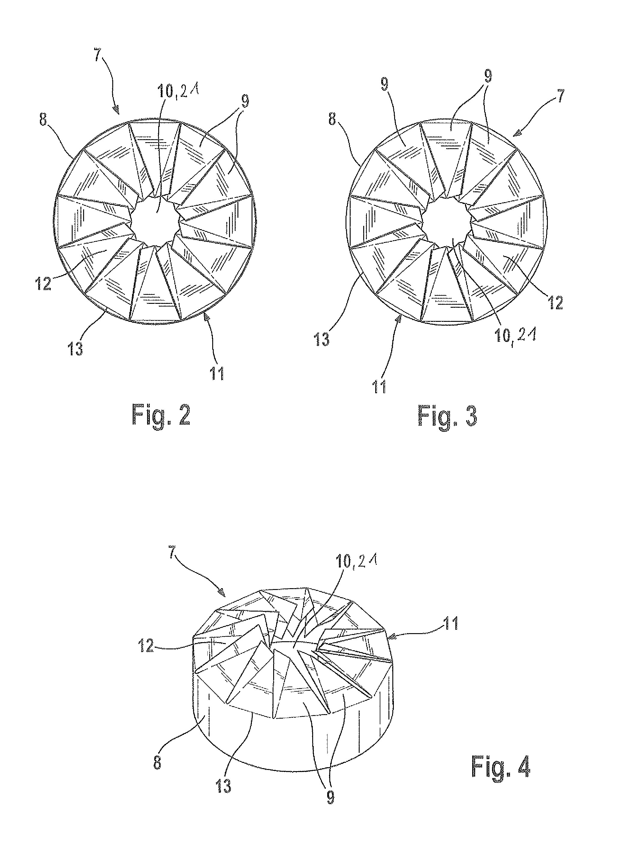
[0007]The present invention is based on the general idea of manufacturing the mixing and / or evaporating device from a single sheet metal body only, on which a tubular body and blades projecting therefrom radially inwardly are formed for this purpose. The mixing and / or evaporating device can be manufactured at a comparatively low cost as a result. The blades are arranged and designed according to the present invention specifically in such a way that they have an angle of incidence in relation to the axial direction of the tubular body. The resistance to flow is increased hereby in the area of the blades and a twist is generated. The twist in the exhaust gas stream generates swirling, which supports the evaporation of the possibly liquid educt, on the one hand, and improves the homogenization of the mixture, on the other hand.
[0008]The blades may be advantageously arranged and designed such that they overlap in the circumferential direction, doing so such that a coaxially arranged surface, which is flat (level) in the axial direction, is formed. Breakthrough of liquid droplets through the mixer structure is avoided due to the formation of such an flat surface. The droplets impact on the blades in the surface and can evaporate more easily as a result.
[0009]According to a variant, the blades may be designed and arranged such that the surface formed by the overlapping of the blades is an annular surface, which encloses a central core area. It becomes possible as a result to design the core area and the annular surface differently from the fluidic point of view. In particular, it is possible to design and arrange the blades such that a lower resistance to flow will become established in the core area than in the area of the annular surface. The pressure can be lowered as a result in the core area, which can be utilized to accelerate the flow of the exhaust gas in the center. The increased velocity of flow in the center facilitates the evaporation of the liquid jet. It is especially advantageous now to direct the liquid jet such that it will reach the blades radially outside the central core area.

Problems solved by technology

The consequence is a reduced mode of action as well the risk of damage.

Method used


Image

  • Mixing and/or evaporating device and process for manufacturing same
  • Mixing and/or evaporating device and process for manufacturing same
  • Mixing and/or evaporating device and process for manufacturing same

Examples


Embodiment Construction

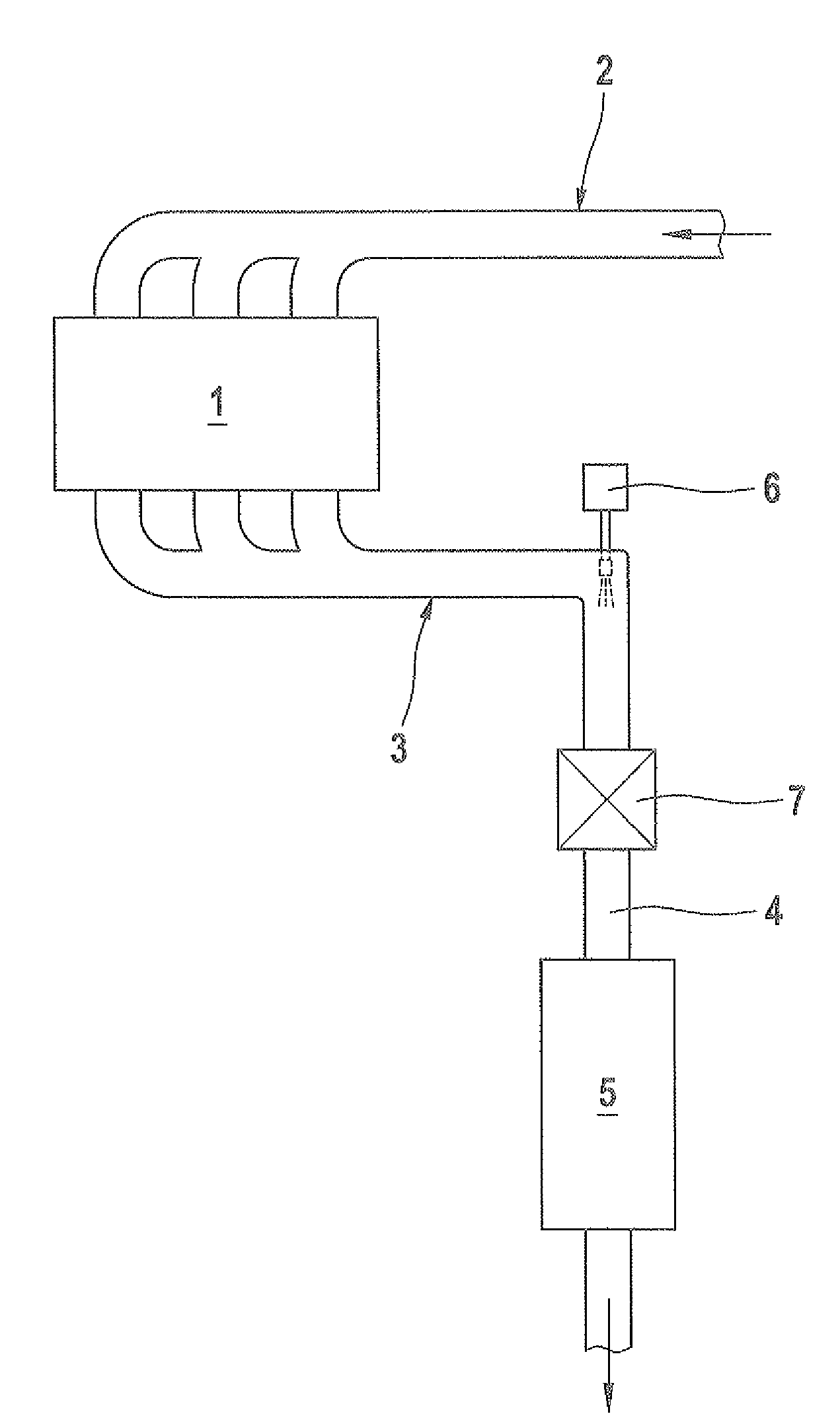
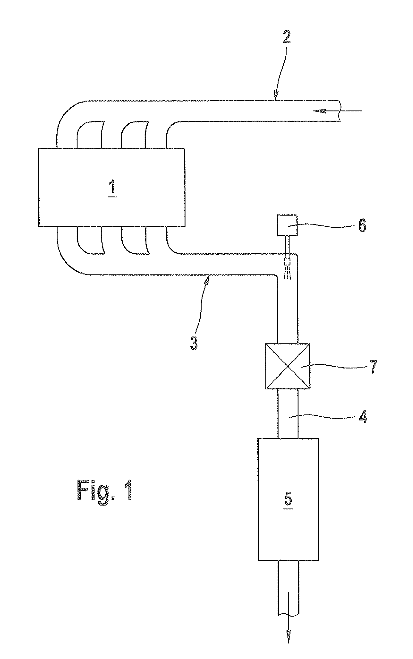
[0038]Referring to the drawings in particular, FIG. 1 shows an internal combustion engine 1, which may be arranged, for example, in a motor vehicle, and has a fresh gas system 2 for being supplied with fresh gas, preferably air, and an exhaust system 3 for removing exhaust gas. Such an exhaust system 3 comprises an exhaust gas line 4, which removes the exhaust gas formed in the internal combustion engine 1 during the operation of the internal combustion engine 1 from the internal combustion engine 1. The exhaust system 3 may have at least one exhaust treatment means 5, which is arranged in the exhaust gas line 4. This exhaust gas treatment means 5 may be, e.g., an oxidation catalyst, an NOx storage catalyst, a hydrolysis reactor, an SCR catalyst or a particle filter. One or more of the means may likewise be accommodated in a common housing, especially in conjunction with a muffler. Furthermore, the exhaust system 3 has an injection means 6, which is designed to inject a liquid educt...


PUM

PropertyMeasurementUnit
Temperatureaaaaaaaaaa
Angleaaaaaaaaaa
Electrical resistanceaaaaaaaaaa

Abstract

A mixing and / or evaporating device (7) is provided for an exhaust system (3) of an internal combustion engine (1), especially in a motor vehicle. The mixing and / or evaporating device (7) has a tubular body (8), at one axial end of which a plurality of blades (9) are arranged, which blades are located adjacent to each other in the circumferential direction, project radially inwardly and have angles of incidence in relation to one another in the axial direction. For manufacture at a low cost, the tubular body (8) is manufactured together with the blades (9) from a single sheet metal body (11) by shaping.

Description

CROSS REFERENCE TO RELATED APPLICATIONS[0001]This application claims the benefit of priority under 35 U.S.C. § 119 of German Patent Application 10 2007 028 449.9 filed Jun. 18, 2008, the entire contents of which are incorporated herein by reference.FIELD OF THE INVENTION[0002]The present invention pertains to a mixing and / or evaporating device for an exhaust system of an internal combustion engine, especially in a motor vehicle. The present invention pertains, in addition, to a process for manufacturing such a mixing and / or evaporating device as well as an exhaust system equipped with such a mixing and / or evaporating device.BACKGROUND OF THE INVENTION[0003]It may be necessary for various reasons in exhaust systems of internal combustion engines to inject a liquid educt into the exhaust gas stream. For example, fuel may be injected into the exhaust gas stream upstream of an oxidation catalyst in order to induce an exothermal combustion reaction at an oxidation catalyst arranged downs...

Claims


Application Information

Patent Timeline
IPC IPC(8): F02M29/02
CPCB01F3/04049B01F5/0451B01F5/0616F01N3/021F01N3/2066F01N3/2892F01N2240/20F01N2240/40F01N2610/02F01N2610/03Y02A50/20B01F23/2132B01F25/3131B01F25/4315
Inventor WIRTH, GEORGNEUMANN, FELIX
Owner EBERSPACHER EXHAUST TECH GMBH & CO KG
Why Eureka
Eureka Blog
Learn More