Device and Method for Separating Magnetic or Magnetizable Particles form a Liquid

a technology of magnetic or magnetizable particles and liquid separation, which is applied in the direction of high gradient magnetic separators, electrostatic separation, water/sludge/sewage treatment, etc., can solve the problems of high material consumption, inconvenient removing of magnetic particles from reaction vessels, and inability to manage or pay for a purely manual handling of large numbers of samples, etc., to achieve small elution volumes

Active Publication Date: 2008-12-18
CHEMAGEN BIOPOLYMER TECH AKTIENGES
View PDF9 Cites 67 Cited by
  • Summary
  • Abstract
  • Description
  • Claims
  • Application Information

AI Technical Summary

Benefits of technology

[0029]By positioning a permanent magnet, which may also be composed of a plurality of individual magnets, a substantially homogeneous magnetic field is produced. In this way it is possible to dispose a larger number of bars, for instance in several rows, with the magnetic field being approximately of the same size at each of the bars; this is of particular advantage with a view to the reproducibility of high-throughput processes. A furth

Problems solved by technology

This creates the conditions required for efficient, low-cost screening at a high sample throughput, which is extremely important for applications in molecular-genetic studies or in the field of medical diagnostics, for example, as it is practically impossible to manage or to pay for a purely manual handling of very large numbers of samples.
These devices are, however, not suitable for removing the magnetic particles from a reaction vessel.
This is a disadvantage as it entails high material consumption (disposable pipette tips).
Furthermore, it is unavoidable that individual magnetic particles are also sucked off, thus leading to a high error rate.
Other errors can be caused by liquids dripping down, leading to cross-contamination.
A disadvantage of this device is that the excitation coil requires a relatively large space, which results in limitations of design and construction.
In addition, the positioning as well

Method used


Image

  • Device and Method for Separating Magnetic or Magnetizable Particles form a Liquid
  • Device and Method for Separating Magnetic or Magnetizable Particles form a Liquid
  • Device and Method for Separating Magnetic or Magnetizable Particles form a Liquid

Examples


Embodiment Construction

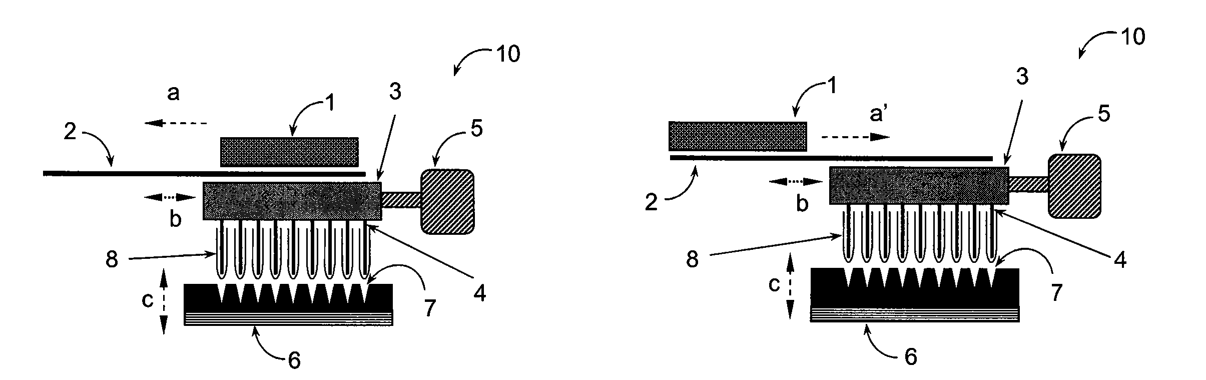
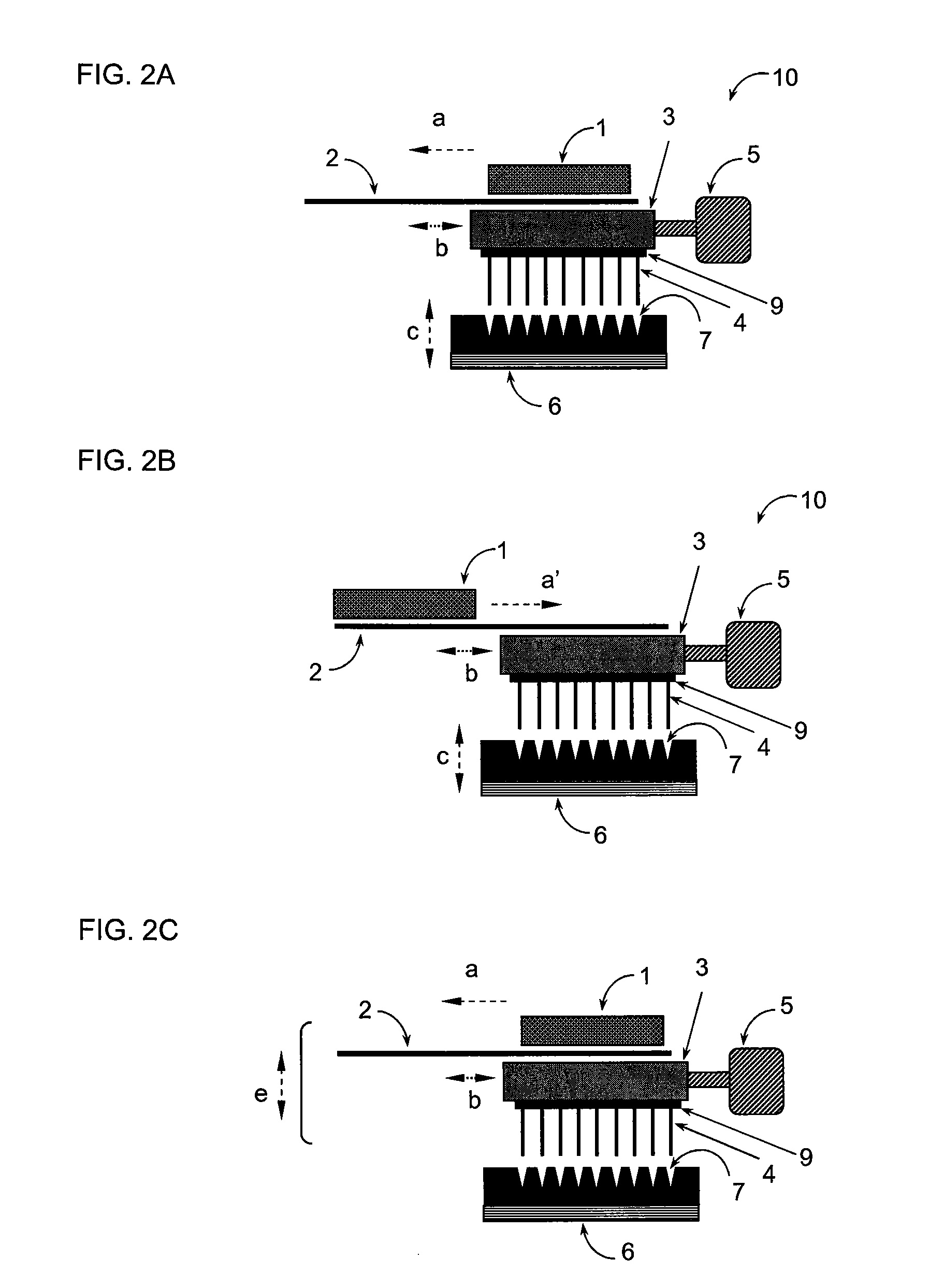
[0038]Basically, any hard-magnetic materials known to the person skilled in the art may be used to produce the permanent magnets, particularly ferrite, Al—Ni—Co alloys and rare earth magnets (preferably NdFeB); such magnetic materials and magnets are commercially available from various manufacturers.

[0039]The number of magnetizable bars attached to the head piece depends on the maximum number of samples, that is, on the maximum number of recesses (“wells”) in the liquid containers, which are to be treated simultaneously. As containers, microtiter plates are used with preference, especially those with 96, 384 or 1536 wells, so that corresponding numbers of magnetizable bars are provided for those cases. Furthermore, also suitable as containers are sample tubes or reaction vessels of a volume of, for example, 0.015 to 100 ml; these can be treated individually or in groups, in each case in combination with magnetizable bars adapted thereto.

[0040]The magnetizable bars, optionally the he...


PUM

PropertyMeasurementUnit
Pressureaaaaaaaaaa
Volumeaaaaaaaaaa
Magnetismaaaaaaaaaa

Abstract

A device (10) is provided for separating magnetic or magnetizable particles from a liquid by using a magnetic field. The device includes a head piece (3) with one or more magnetizable bars (4) which is/are permanently or detachably connected with the head piece (3), as well as one or more permanent magnets (1) whose relative position with respect to the head piece can be changed by a predeterminable movement of the magnet(s) or/and by a predeterminable movement of the head piece.

Description

CROSS-REFERENCE TO RELATED APPLICATIONS[0001]This application is a Section 371 of International Application No. PCT / EP2006 / 000747, filed Jan. 28, 2006, which was published in the German language on Aug. 10, 2006, under International Publication No. WO 2006 / 081995 A1 and the disclosure of which is incorporated herein by reference.BACKGROUND OF THE INVENTION[0002]The invention relates to devices for separating and resuspending magnetic or magnetizable particles from liquids by means of a magnetic field produced by one or more permanent magnets.[0003]The invention further relates to methods for separating magnetic or magnetizable particles from liquids and to the mixing and resuspending of magnetic or magnetizable particles in liquids by means of a magnetic field produced by one or more permanent magnets. The devices and methods can be used, for example, for applications in drug development, biochemistry, molecular genetics, microbiology, medical diagnostics and forensic medicine.[0004...

Claims


Application Information

Patent Timeline
IPC IPC(8): B03C1/30
CPCB03C1/286B03C1/30B03C1/06B03C2201/26B03C2201/22B03C1/033B03C2201/18
Inventor BRASSARD, LOTHAR A
Owner CHEMAGEN BIOPOLYMER TECH AKTIENGES
Why Eureka
Try Eureka